Just looking at some stuff .
The VCO varicap used in the old Unidens was a MV201 . Seems to have a range of between 3 and 14pF .
https://www.web-bcs.com/diode/dv/ma/MV201.php
Some of the Ranger models used a SVC251 which , if I'm reading it right , had a capacitance of between 11 and 38pF
http://pdf.datasheetcatalog.com/datashe ... 1SPA-D.PDF
So , here's my question . If the varicap fails on my old 360FM , am I able to replace it with a SVC251 without having to add or remove other caps in the circuit ?
Also . Is there a modern general equivalent , like the BB809 for example , that I can use in both types of radios ?
Sammy
VCO Varicaps
-
cb4ever104

- Legend

- Posts: 6561
- Joined: 28 Jul 2011, 21:26
- Location: España
VCO Varicaps
30TM060
Paul aka "Sammy". (108) PY60 Old Paisley DX Group (RIP Rab Markie)
Ex GM0 , now EA5 .
Handle "Fortune Hunter" back in "the day"
Radios ....? Anything that says "TAIWAN R.O.C" on the back.
Paul aka "Sammy". (108) PY60 Old Paisley DX Group (RIP Rab Markie)
Ex GM0 , now EA5 .
Handle "Fortune Hunter" back in "the day"
Radios ....? Anything that says "TAIWAN R.O.C" on the back.
-
Otter

- Veteran

- Posts: 3365
- Joined: 04 Apr 2008, 21:42
- Call Sign: 26TM439
Re: VCO Varicaps
I would try to get something as close as possible to the original. I haven't tried this stuff, but if your varicap changes more for the same change of voltage it will change the MHz/V of your loop and it may go unstable. Also is it doesn't actually go unstable you may get other issues.
"To this day the words Stirling bridge conjour pride in every Scotsman's heart, while to an Englishman those same words conjour literally no feelings at all." - Cunk on Britain S1 E1
-
cb4ever104
- Legend
- Posts: 6561
- Joined: 28 Jul 2011, 21:26
- Location: España
Re: VCO Varicaps
The BA111 is marked as an equivalent for the MV201
https://english.electronica-pt.com/comp ... ?ref=MV201
but that's rated as 35-55pF
https://www.web-bcs.com/diode/dv/ba/BA111.php
so I'm not sure if that would cause issues or not . I was just curious as these original parts are getting harder and harder to source .
Sammy
https://english.electronica-pt.com/comp ... ?ref=MV201
but that's rated as 35-55pF
https://www.web-bcs.com/diode/dv/ba/BA111.php
so I'm not sure if that would cause issues or not . I was just curious as these original parts are getting harder and harder to source .
Sammy
30TM060
Paul aka "Sammy". (108) PY60 Old Paisley DX Group (RIP Rab Markie)
Ex GM0 , now EA5 .
Handle "Fortune Hunter" back in "the day"
Radios ....? Anything that says "TAIWAN R.O.C" on the back.
Paul aka "Sammy". (108) PY60 Old Paisley DX Group (RIP Rab Markie)
Ex GM0 , now EA5 .
Handle "Fortune Hunter" back in "the day"
Radios ....? Anything that says "TAIWAN R.O.C" on the back.
-
lbcomms
- Radio Addict

- Posts: 509
- Joined: 04 Oct 2015, 08:10
- Location: Sydney, Australia
Re: VCO Varicaps
We use the BB809 to replace nearly all of the older types. 75% of the time they go straight in and just need a touch-up of the VCO screw to set the tuning voltage, but the other 25% need one or two caps changing to make the circuit match the behavior of the original part. Easy to do, the Uniden uPD2824 (i.e. Realistic TRC451, AX/AR144, etc) as an example:cb4ever104 wrote: ↑19 May 2022, 09:10 so I'm not sure if that would cause issues or not . I was just curious as these original parts are getting harder and harder to source .
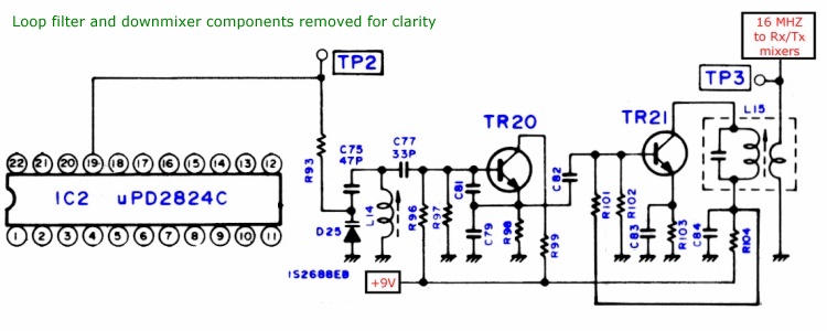
The VCO tuning voltage is set in this case by pin 19 of the PLL. It will raise the voltage to raise the VCO frequency and conversely lower it to lower the frequency until it locks the loop. The only two components that may need changing are C75 and C77.
C75 sets the gain (MHz/V) of the loop. If you want the VCO to cover more range for a given voltage change, increase it. On the other hand, changing the varicap might increase the gain too much - for example if it's only a 40 channel set and the VCO tuning voltage is 2V on channel 1 and 2.3V on 40, then reduce the value of that cap to reduce the loop gain so it varies from say 1.5V on 1 and 3V on 40. This will help stability and also keep phase noise (which can show as rough SSB audio and/or degraded receiver selectivity) to the level it was with the original varicap.
C77 sets the centre frequency of the VCO. If after changing the varicap and/or changing C75, you find the adjustment slug is either all the way down in the can or mostly sticking right out, then change C77 to re-centre the VCO with a sensible slug position, say 1-2mm below the top level of the can. Decrease the cap to raise the centre frequency, increase it to lower the frequency.
It only takes a few minutes if you "jury rig" the circuit by replacing the PLL tuning voltage with one source from a pot.
In the above example, isolate pin 19 and connect the PLL chip side of R93 to the wiper (centre terminal) of the pot, and connect the hot and cold pot terminals to +9V and ground respectively. The pot can then be used to control the VCO frequency. Calculate the centre frequency by subtracting the centre channel frequency from the radios IF - in the case of the TRC-451, 27.205 - 10.695 = 16.51 MHz. Set the slug to 2mm below the top level of the can. Always do C75 first, for the 40 channel radio about 250-500KHz/V works well. You'll need 1 MHz /V or so for a multi-band radio for full coverage.
Once that's done, set the pot for say 3V, and don't adjust the slug position. Change C77 to set the VCO frequency to about 16.5 MHz in the case of the '451. Once that is done, remove the pot and reinstate the connection to pin 19, and make a small slug adjustment to precisely set the VCO tuning voltage.
If you only have a counter that connects to the antenna socket, the same technique can be used, but you'll have the additional step of lifting the component (usually a diode) that connects to the lock detect pin temporarily, to allow the radio to transmit when its frequency is being controlled by the pot.
Sounds a bit long winded, but only takes a few minutes after a bit of practice and you only need to carry on varactor type...
-
cb4ever104
- Legend
- Posts: 6561
- Joined: 28 Jul 2011, 21:26
- Location: España
Re: VCO Varicaps
Hi Sue.
Excellent explanation as usual . Many thanks for replying to the thread !
Excellent explanation as usual . Many thanks for replying to the thread !
30TM060
Paul aka "Sammy". (108) PY60 Old Paisley DX Group (RIP Rab Markie)
Ex GM0 , now EA5 .
Handle "Fortune Hunter" back in "the day"
Radios ....? Anything that says "TAIWAN R.O.C" on the back.
Paul aka "Sammy". (108) PY60 Old Paisley DX Group (RIP Rab Markie)
Ex GM0 , now EA5 .
Handle "Fortune Hunter" back in "the day"
Radios ....? Anything that says "TAIWAN R.O.C" on the back.
-
cb4ever104
- Legend
- Posts: 6561
- Joined: 28 Jul 2011, 21:26
- Location: España
Re: VCO Varicaps
Hi Sue .
Can I just pick your brain again a bit . Here's the schematic for the Cobra 148 GTL-DX mk2 . Any idea why they used 2 varicaps in this circuit ? I'm assuming (no doubt incorrectly) that it's because they couldn't get the right amount of capacitance from just 1 ? I know I've got the FM TX audio coming in to that circuit as well , but I don't think that's got anything to do with that .
Thx
You do not have the required permissions to view the files attached to this post.
30TM060
Paul aka "Sammy". (108) PY60 Old Paisley DX Group (RIP Rab Markie)
Ex GM0 , now EA5 .
Handle "Fortune Hunter" back in "the day"
Radios ....? Anything that says "TAIWAN R.O.C" on the back.
Paul aka "Sammy". (108) PY60 Old Paisley DX Group (RIP Rab Markie)
Ex GM0 , now EA5 .
Handle "Fortune Hunter" back in "the day"
Radios ....? Anything that says "TAIWAN R.O.C" on the back.
-
lbcomms
- Radio Addict
- Posts: 509
- Joined: 04 Oct 2015, 08:10
- Location: Sydney, Australia
Re: VCO Varicaps
To get more range from the VCO - they are just a pair in parallel, so as far as the circuit goes they behave as a single "better" component.
The circuit is essentially the same as the 2824, with more range. C95 (or is it C96, hard to tell on that scan) sets the loop gain (just over twice as high as the 40 channel only 2824) and C103 sets the centre frequency.
For replacement, a single BB809 would probably work, but add the second if the lowest and highest frequency get too close to the voltage limits of the PLL driving it.
-
cb4ever104
- Legend
- Posts: 6561
- Joined: 28 Jul 2011, 21:26
- Location: España
Re: VCO Varicaps
Thanks Sue.... again ! 


30TM060
Paul aka "Sammy". (108) PY60 Old Paisley DX Group (RIP Rab Markie)
Ex GM0 , now EA5 .
Handle "Fortune Hunter" back in "the day"
Radios ....? Anything that says "TAIWAN R.O.C" on the back.
Paul aka "Sammy". (108) PY60 Old Paisley DX Group (RIP Rab Markie)
Ex GM0 , now EA5 .
Handle "Fortune Hunter" back in "the day"
Radios ....? Anything that says "TAIWAN R.O.C" on the back.