cb4ever104 wrote: ↑20 Nov 2021, 13:22
My schematic is different from yours . Think I need to remove C72 as well
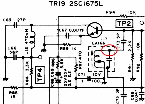
Yes, that's very different to the 2824 radios we have here. You will need to remove C72 in that circuit.
That also explains why the radio still transmitted and received, albeit on the wrong frequency.
The PLL divides the 10.240 by 2 and outputs the result to pin 10. It's a square wave, so it's also full of odd harmonics. The inductor and two capacitors are a bandpass tuned to 15MHz, so they let through the third harmonic (15.360 MHz) and it is then mixed at the transistor with the VCO to produce the downmix signal needed to lock the loop.
26.965 - 10.695 = 16.270, and 16.270 - 15.360 = 0.91 MHz, exactly whats needed to lock the loop on FCC channel 1. The original SSB offset inductors and clarifier also connect to the 10.24 to change things a bit for SSB use.
BUT: when you remove C72 and there is no output from the 5351, there will be no downmix signal at all and the radio will quit.
Find why there is no output from the 5351 board before going any further. It's either faulty / damaged, or not wired correctly. Disconnect the output from CLK1 and measure with a scope and frequency counter. You should have a 3V P-P waveform at CLK1 at all times around 15MHz, and 25MHz at CLK0 when it's enabled at the PC app.
Once you have the waveform on the 5351 board, remove C72 and connect CLK1 to the L13 hole that goes to C73. The radio should come to life.
Once that's done, use the PC app to configure the 25MHz, offsets, and clarifier.