This is a slightly different version to suit the uPD2824 radios that appeared in the early 80's, several years after the 858 disappeared.
Repeated warning - this is intended for people experienced with RF and digital electronics and are comfortable inside a radio. It is NOT a beginner "cut the orange wire and solder it to the green one to make your radio put out 50 watts" style change. This is a "work in progress" project still under development, and may (probably does!) contain bugs. So don't do this on your primary or only radio just yet. Any bug or success reports gratefully appreciated though!!!
The requirements we set for this project are similar to the 858 version. Only #1 has changed for the uPD2824 - these are not as valuable as the 858 when in average condition, so it's not as critical the mods be reversible. The example used in the prototype below cost only $45 from a secondhand store in good physical but electrically partially functional condition. We also broke our "no SMT" rule for this chassis, but only for the broadbanding part because we used components we already had on hand. Broadbanding can be done in the same way with conventional through hole components, or just skipped entirely if you only wanted an extra 40 channels coverage.
Requirements:
1) Only basic physical mods needed, no cut tracks / drilled holes / dremel butchery.
2) No SMT. Not everyone tinkering with old radios has the ability or equipment to work with these tiny devices.
3) No sensitive analog / RF components such as coils / crystals, and little or no wiring where length of cables is critical.
4) Able to give large amounts of "slide" or add dual coarse/fine clarifiers without drift or instability.
5) All components currently / readily available through online sellers such as Ebay / Amazon, or at a pinch Mouser / E14 / Digikey.
6) Cost of parts under AUS$25 (20 USD / Euro / UKP) including the programming hardware.
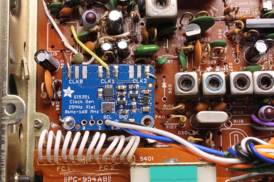
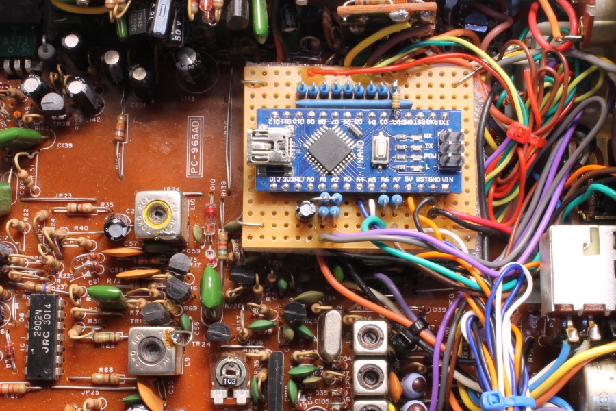
Only way to achieve this was by going digital. If you've never used a programmable microcontroller before you might have a bit of a learning curve with these. The only semi-critical piece of equipment needed is a bench type frequency counter, at least 7 digits of resolution will be needed, 8 is better (i.e 1Hz resolution at 30 MHz). Having other high end gear (scope, spectrum analyzer) is nice to align the rest the radio, but is not needed to install the mod.
The oscillator used is claimed to be stable at 10ppm, this works out to within 150Hz at the 27Mhz output frequency. If there is not too much temperature variation at the radio, such as in a base station, it's adequate for SSB use. For situations where there are extremes - such as in a car here in Australia where it can get to 50 degrees C (122 Fahrenheit) in the daytime and near freezing at night - we made a stabilizer to make it stable to within a few Hz. It's not included here as it involves tiny SMT component changes but we'll post this later for anyone that wants extreme stability and is able to do the soldering needed.
With this chassis, the 10.695 MHz carrier oscillator stage (crystal and 3 adjustable inductors) was thought to be more of a potential drift source, but this turned out to be a non-issue when it was tested after the mods were completed in an environmental chamber (basically a big programmable combination oven and refrigerator). The frequency was set to spot on at at 20 degrees C (68 degrees F), then measured for change after an hour at each one.
-10 degrees C (14 degrees F): -30Hz
+10 degrees C (50 degrees F): -20Hz
+20 degrees C (68 degrees F): 0Hz (set point)
+30 degrees C (86 degrees F): +15Hz
+40 degrees C (104 degrees F): +35Hz
+50 degrees C (122 degrees F): +65Hz
+60 degrees C (140 degrees F): +80Hz
+75 degrees C (167 degrees F): +150Hz
As long as the radio stays in the 0 to 35 degree (0 to 95 Fahrenheit) range the drift will be barely noticeable. The high stab version should be good for no more than 5Hz drift across the above temperature range, but will at least double the cost of the components needed to do the conversion.
The conversion was done in 3 stages - getting it working correctly as a standard radio, broadbanding it to cover the required frequency range, and finally expanding the frequency coverage. The second stage proved to be the most problematic, this chassis is rather narrow banded, but we got there in the end.
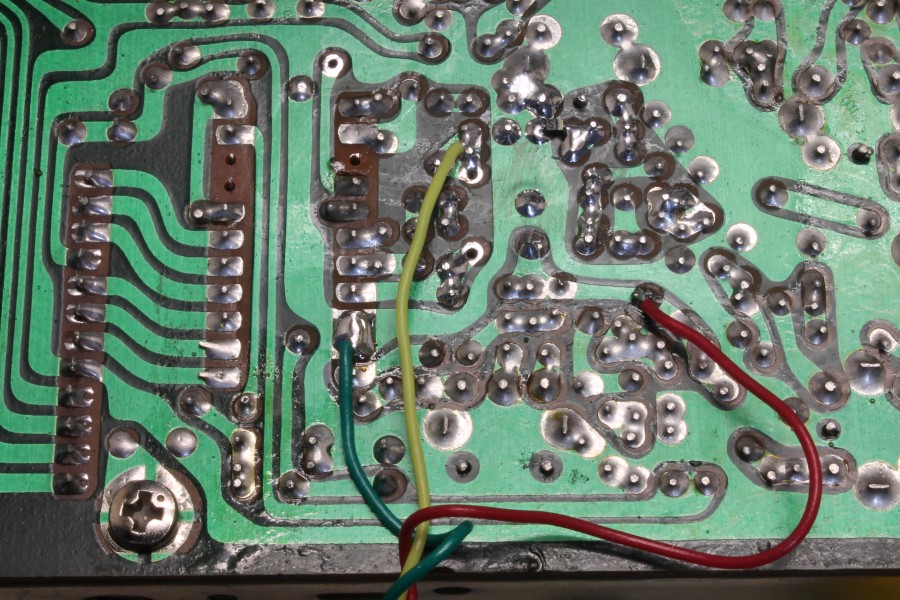
Stage one - repair the radio

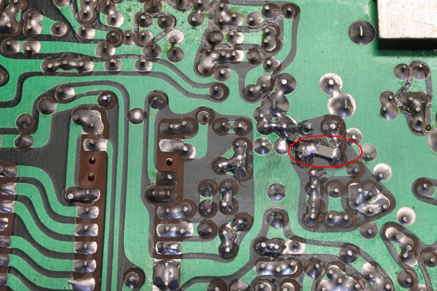
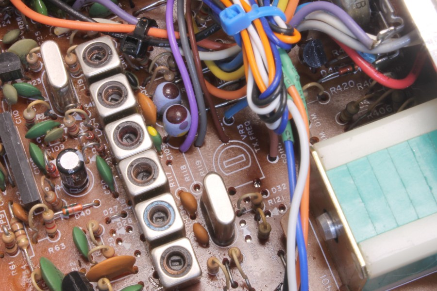
The old 10V electrolytics had to go
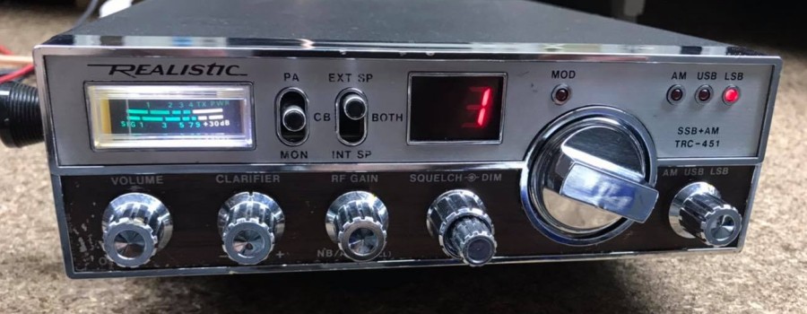
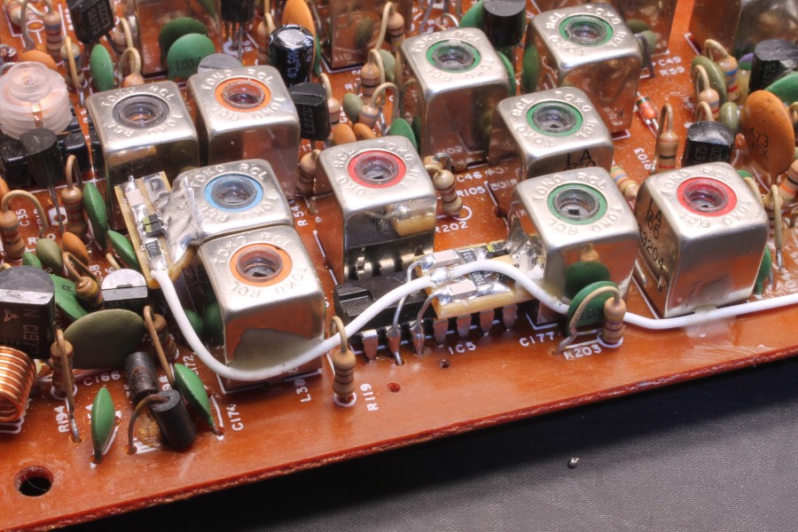
The radio after repairing
First step was to get the radio working as a standard 40 channel unit. It had good AM carrier but low / distorted modulation, less than 5W on SSB with "fuzzy" audio, and a long delay on Rx when first turned on.
Fortunately this example had never been previously repaired or modified, and just needed a fresh set of electrolytics and a meter light. A small modification was done to allow it to receive without having to have a mic plugged in (requested by the owner so he could later wire up a ham mike that does not have Rx switching contacts), change one transistor and add another. A bit of deoxit in the controls and a full alignment and it was working better than the day it was sold.
The radio was returned to the owner to use for a week to make sure there were no intermittent faults lurking that could have caused headaches later on.