Computer Power Supply Converted to 13.8V for Radio
Posted: 27 Feb 2011, 06:11
Hey,
Picked up a new 400Watt PC ATX Power Supply and converted it to 13.8V using the instructions at: http://www.radiorampage.com/techpages/comppsu.php It was pretty easy, but I think it still needs a little more work.
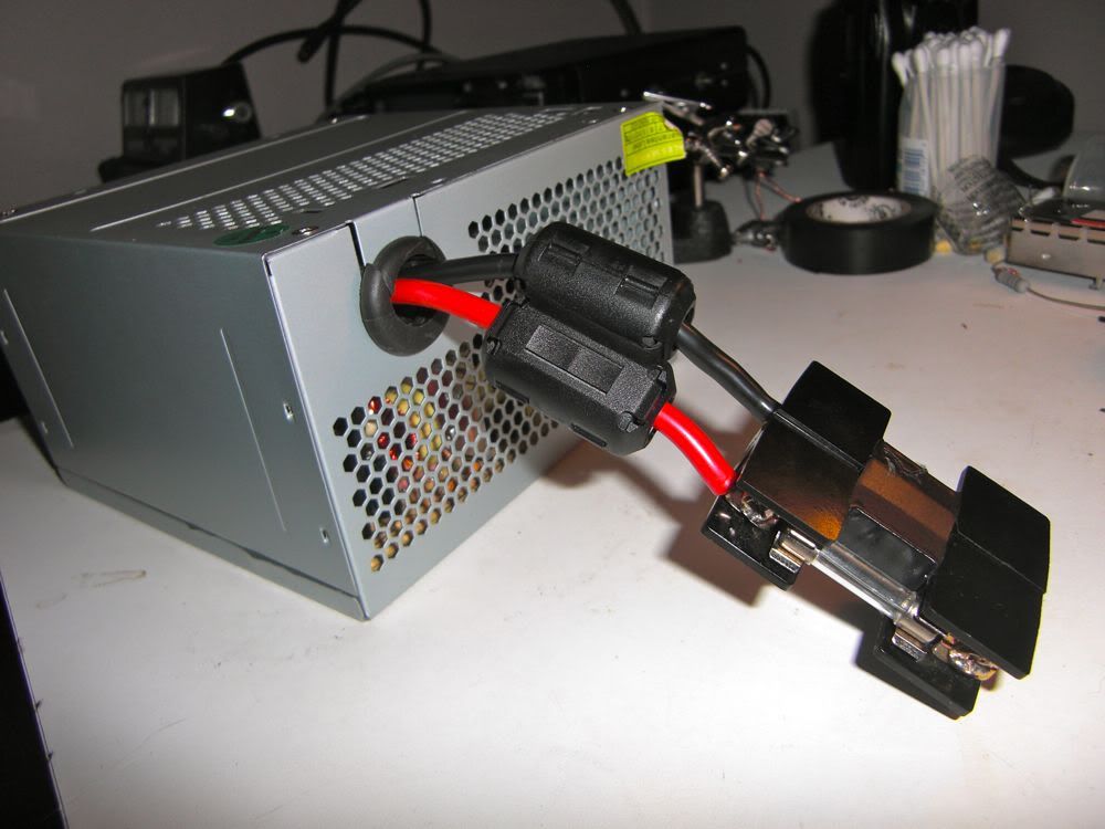
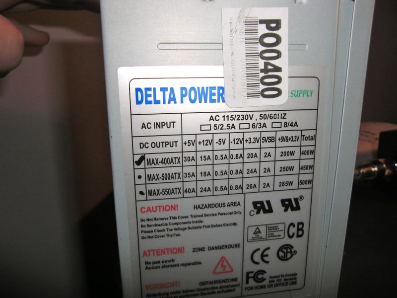
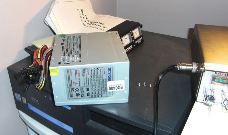
Here's the PSU I got. $15 (Canadian) + Tax:
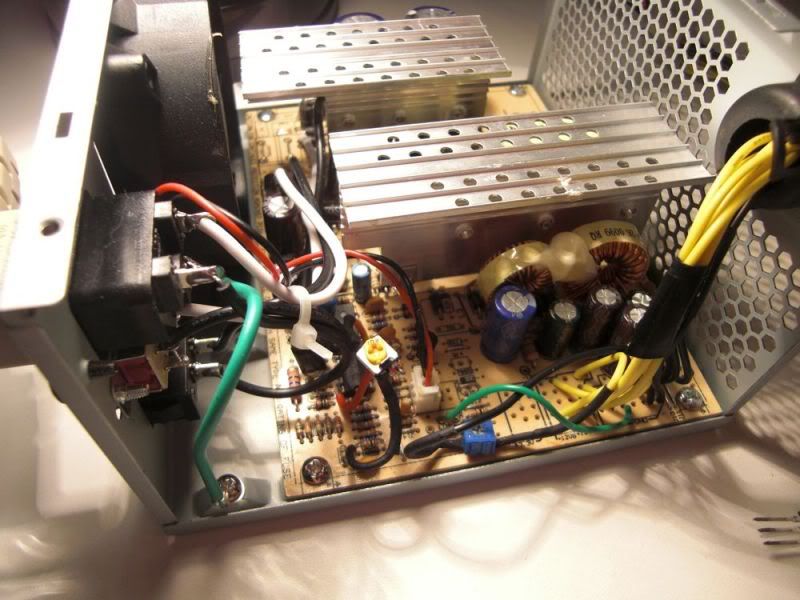
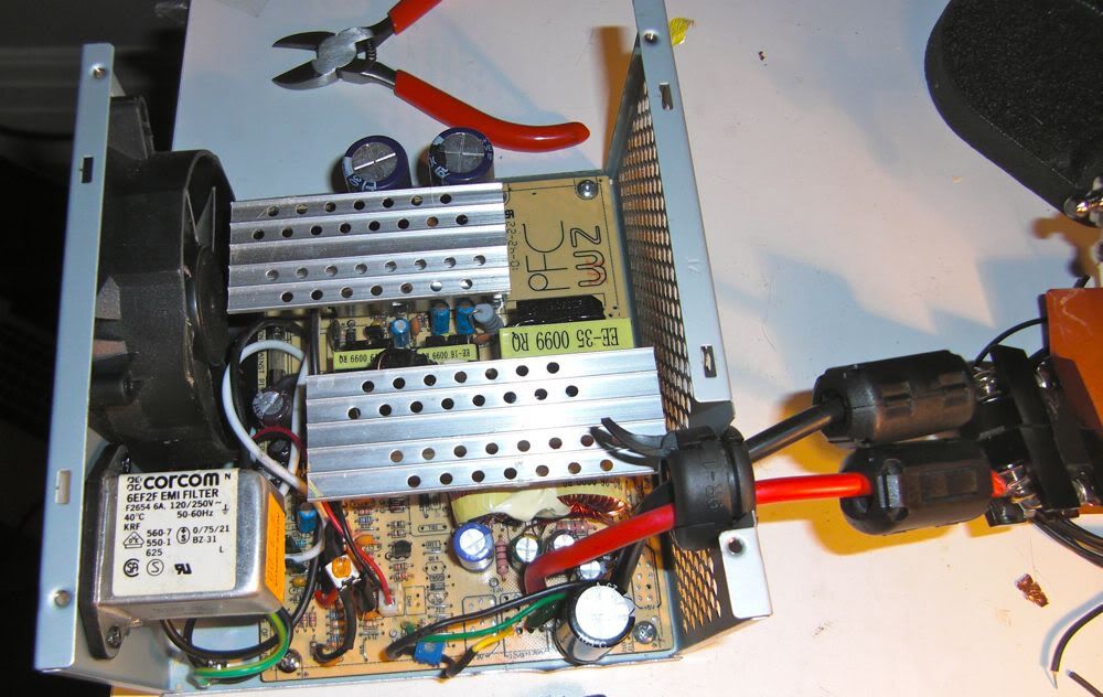
Case Removed:
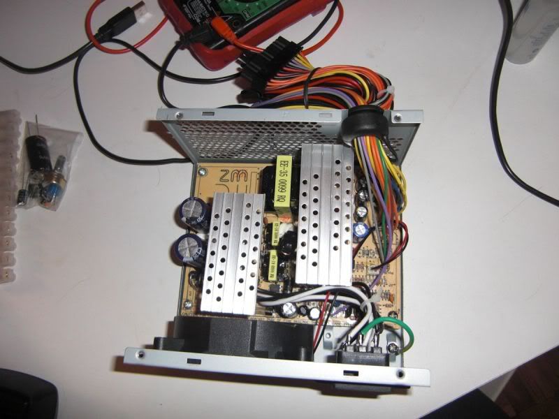
The capacitors in here can hold a deadly charge even after turned off. I always left it for a minute after turning off before opening. I also connected a load to the output, but kept switch on and AC input disconnected to try and use up some of the held charge. When handling I was careful not to touch anything on the AC side (top or bottom).
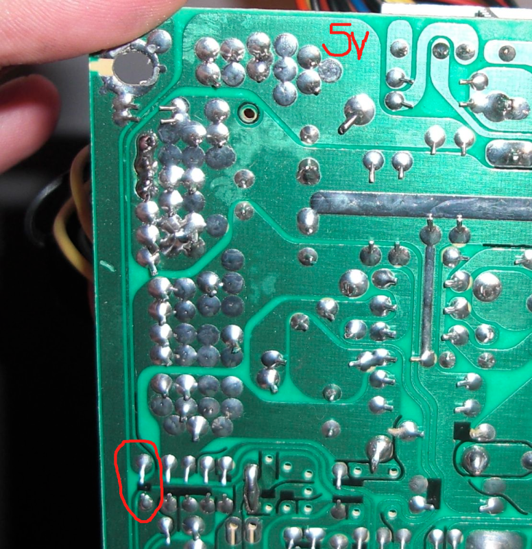
Here's the underside of the board:
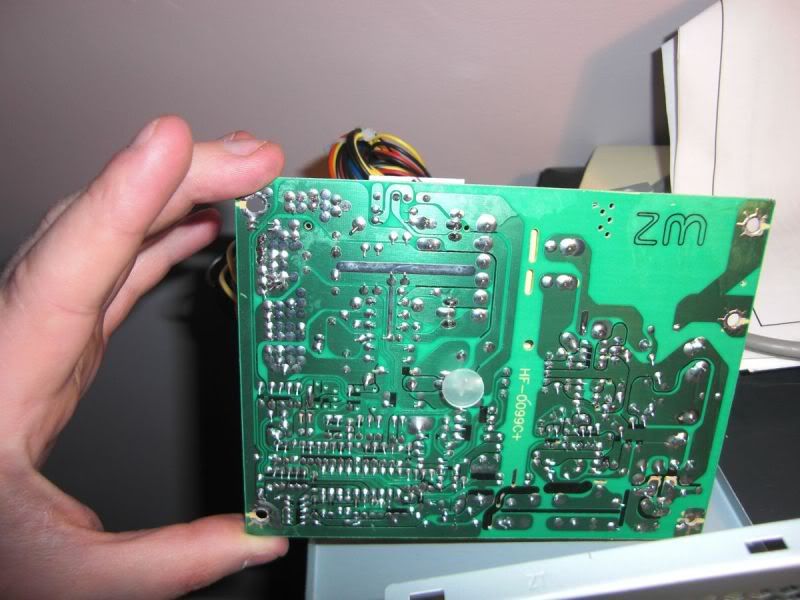
As per the tutorial I located the track that ran from the 5V wires down to the voltage control circuits. It was pretty easy and there was a bit of wire on the top of the board connecting it so I just removed that to prevent the 5V output controlling the total voltage.
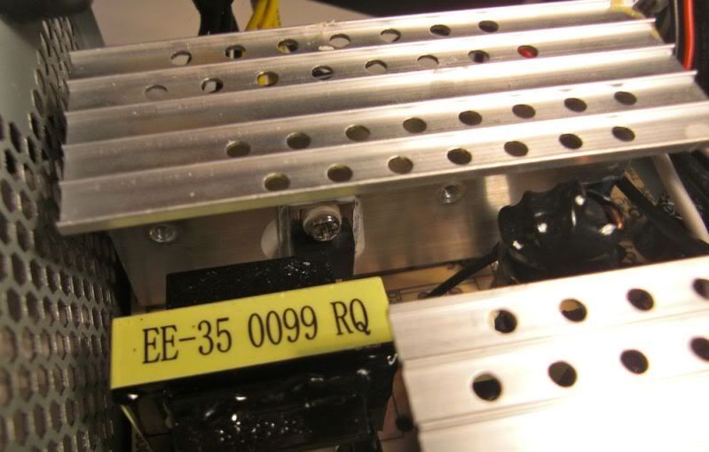
You can see in the red circled area the underside of the jumpers connections:
Red arrow here show's where I removed the jumper:
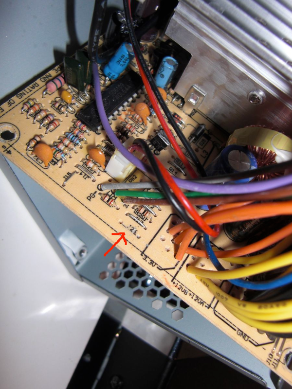
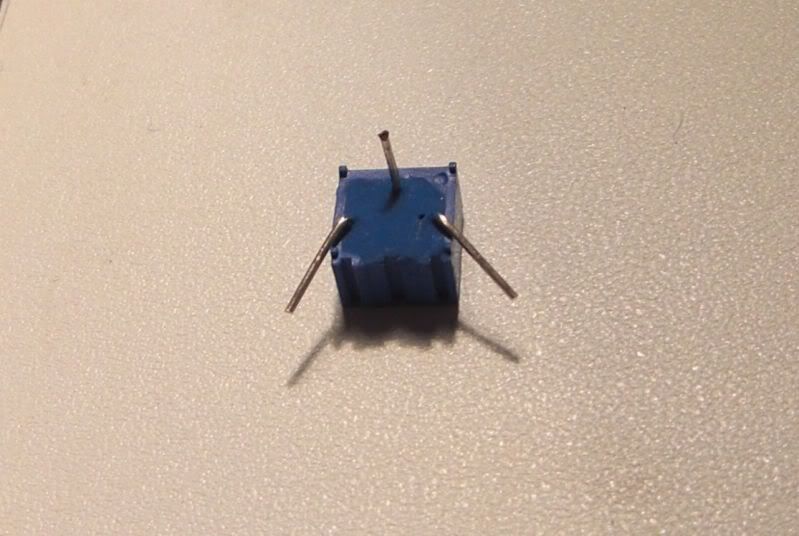
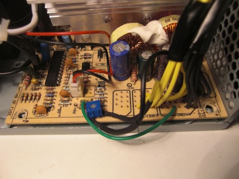
I got a 1k trim pot and bent the pin 1 and pin 3 legs out, leaving the wiper pin straight. I put the wiper pin in one of the holes on the PCB left by removing the jumper. I was sure to use the voltage control side, not the side leading up to the 5V output wires.
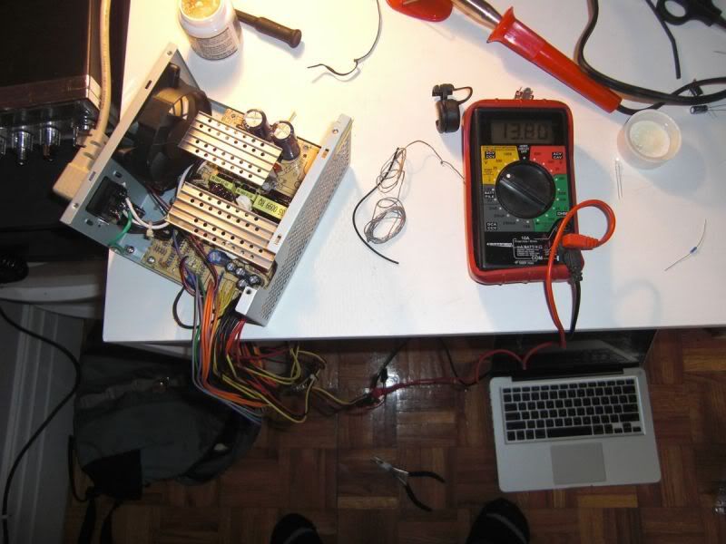
I connected a wire from the 12V section to pin 3 and from 0V to pin 1. I put some heatshrink on them too to prevent any short circuits. After that it was time to test it to see if it worked. I set the trim pot to the middle, bridged the green wire and a black wire on the ATX plug (to simulate the computer power button being on), connected a volt meter across the 12V (yellow) and 0V (black) pins of one of the molex connectors and powered up.
The supply immediately came to life and I was pleasantly surprised at how quiet the fan was for a cheap PSU. I slowly turning the trim pot until I got 13.8V on the volt meter.
At one point I went a bit too high and the supply shut down. After this happened it took me a while to get it going again. You need to move the trim pot with the supply turned off, and leave it off with the power disconnected for at least a minute before it will turn back on. If the trim pot is still not within the require range it won't turn on and you need to adjust and wait another minute to try again. I almost thought I'd killed the supply but I found the sweet pot on the trim pot eventually and she powered back up.
Then I did some tidy up. I chopped off all connectors, desoldered all unnecessary wires and twisted the 6 yellow together and tinned the end, then did the same with 6 blacks. These go into a connector block which I use to connect to the radio's power cable. I also wired the green wire directly into the 0V section of the board.
I then connected it all back up, and connected it to the radio. I spoke to some local contacts and compared the performance with the PSU and with a car battery. I was told I sounded clearer and louder with the PSU. I checked my power meter and it showed my radio putting out bang on 40Watts on SSB, rather than the 35/36 I was getting with the battery. There was no more noticeable interference using the PSU than with the battery and I specifically asked people I was talking to if there was any buzzing or anything on my transmit audio and was told there was not.
If I did experience interference/noise I was going to bridge some capacitors over the output like the tutorial suggested. The plan was to put them inside the PSU directly on the PCB by soldering them into some of the unused 12V and 0V holes, of which there are quite a few. I presume this PCB is also used for higher end supplies with more power and more connectors.
I was happy it was performing better than the battery I had been using and cost me less than $20 total and an hour or so of work. I stared doing some more testing though and measuring the voltage across the output when I was transmitting at different frequencies. I used FM at all times which shows as a sold 40W on my plug in power meter.
Sometimes I was getting a drop from 13.8 to 13.5 while transmitting. Occasionally it would go down to 12.5V just as I started. I tried this on a few different frequencies and noticed some times it dropped lower, much lower. There were times when the volt meter dropped all the way to 4V, but the radio still seemed to be performing fine. I put a 12V bulb from my van across the output too, and when the volt meter was dropping the bulb brightness did not change so I'm a little confused by this.
I'm going to do some more experimenting tomorrow with it. There are a couple of videos on youtube of another guy who did something similar but used a different technique:
http://www.youtube.com/watch?v=S0JDuiTcMxs&NR=1
He changes the 12V regulator so he can get 30Amps out of it. My supply is rated for 15A at 12V so, will be good for 13A at 13.8V without modification I guess. The manual for my Magnum Delta Force says it uses 6 Amps max so that's plenty. He also removes the 3.3V and 5V regulators and rewinds the toroid with 18 gauge enamelled copper. I got some of this special wire and may do the same. I am not quite sure though if I need to put on the same number of turns, or if I should put on an many turns as I can. First I need to do some more investigations to see if there is a precise pattern as to when the voltage drop during transmit occurs and if it has any negative effects. So far I'm happy though as I can put the battery back in my van and the radio is working better than it did with the battery.
Picked up a new 400Watt PC ATX Power Supply and converted it to 13.8V using the instructions at: http://www.radiorampage.com/techpages/comppsu.php It was pretty easy, but I think it still needs a little more work.
Here's the PSU I got. $15 (Canadian) + Tax:
Case Removed:
The capacitors in here can hold a deadly charge even after turned off. I always left it for a minute after turning off before opening. I also connected a load to the output, but kept switch on and AC input disconnected to try and use up some of the held charge. When handling I was careful not to touch anything on the AC side (top or bottom).
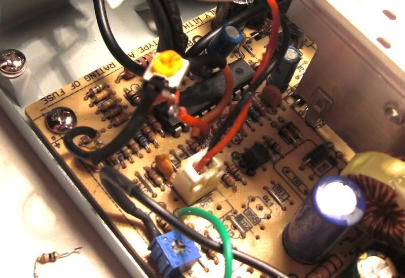
Here's the underside of the board:
As per the tutorial I located the track that ran from the 5V wires down to the voltage control circuits. It was pretty easy and there was a bit of wire on the top of the board connecting it so I just removed that to prevent the 5V output controlling the total voltage.
You can see in the red circled area the underside of the jumpers connections:
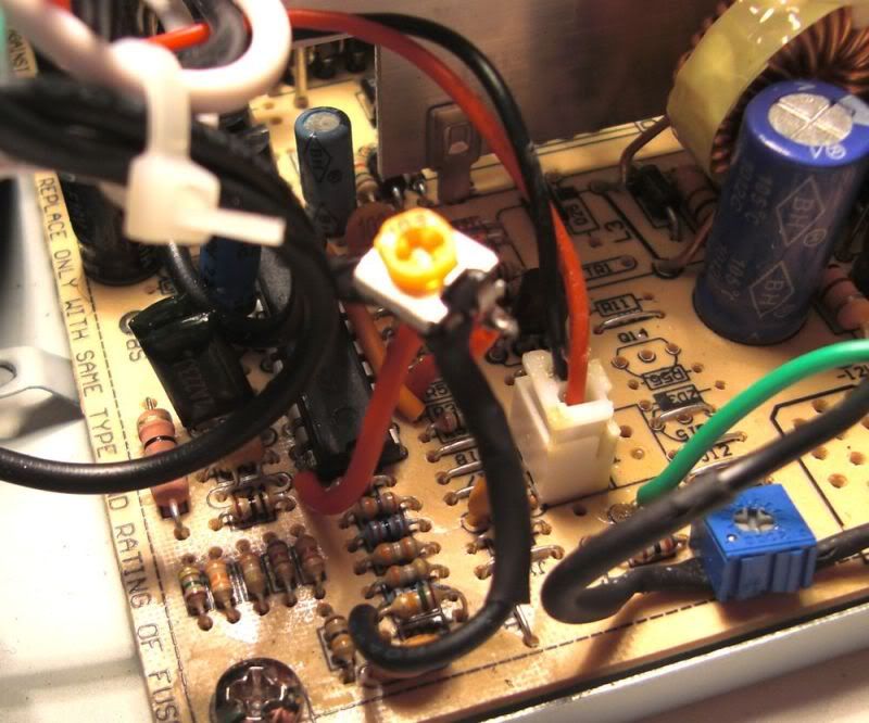
Red arrow here show's where I removed the jumper:
I got a 1k trim pot and bent the pin 1 and pin 3 legs out, leaving the wiper pin straight. I put the wiper pin in one of the holes on the PCB left by removing the jumper. I was sure to use the voltage control side, not the side leading up to the 5V output wires.
I connected a wire from the 12V section to pin 3 and from 0V to pin 1. I put some heatshrink on them too to prevent any short circuits. After that it was time to test it to see if it worked. I set the trim pot to the middle, bridged the green wire and a black wire on the ATX plug (to simulate the computer power button being on), connected a volt meter across the 12V (yellow) and 0V (black) pins of one of the molex connectors and powered up.
The supply immediately came to life and I was pleasantly surprised at how quiet the fan was for a cheap PSU. I slowly turning the trim pot until I got 13.8V on the volt meter.
At one point I went a bit too high and the supply shut down. After this happened it took me a while to get it going again. You need to move the trim pot with the supply turned off, and leave it off with the power disconnected for at least a minute before it will turn back on. If the trim pot is still not within the require range it won't turn on and you need to adjust and wait another minute to try again. I almost thought I'd killed the supply but I found the sweet pot on the trim pot eventually and she powered back up.
Then I did some tidy up. I chopped off all connectors, desoldered all unnecessary wires and twisted the 6 yellow together and tinned the end, then did the same with 6 blacks. These go into a connector block which I use to connect to the radio's power cable. I also wired the green wire directly into the 0V section of the board.
I then connected it all back up, and connected it to the radio. I spoke to some local contacts and compared the performance with the PSU and with a car battery. I was told I sounded clearer and louder with the PSU. I checked my power meter and it showed my radio putting out bang on 40Watts on SSB, rather than the 35/36 I was getting with the battery. There was no more noticeable interference using the PSU than with the battery and I specifically asked people I was talking to if there was any buzzing or anything on my transmit audio and was told there was not.
If I did experience interference/noise I was going to bridge some capacitors over the output like the tutorial suggested. The plan was to put them inside the PSU directly on the PCB by soldering them into some of the unused 12V and 0V holes, of which there are quite a few. I presume this PCB is also used for higher end supplies with more power and more connectors.
I was happy it was performing better than the battery I had been using and cost me less than $20 total and an hour or so of work. I stared doing some more testing though and measuring the voltage across the output when I was transmitting at different frequencies. I used FM at all times which shows as a sold 40W on my plug in power meter.
Sometimes I was getting a drop from 13.8 to 13.5 while transmitting. Occasionally it would go down to 12.5V just as I started. I tried this on a few different frequencies and noticed some times it dropped lower, much lower. There were times when the volt meter dropped all the way to 4V, but the radio still seemed to be performing fine. I put a 12V bulb from my van across the output too, and when the volt meter was dropping the bulb brightness did not change so I'm a little confused by this.
I'm going to do some more experimenting tomorrow with it. There are a couple of videos on youtube of another guy who did something similar but used a different technique:
http://www.youtube.com/watch?v=S0JDuiTcMxs&NR=1
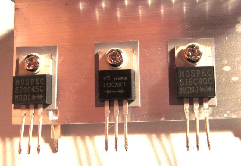
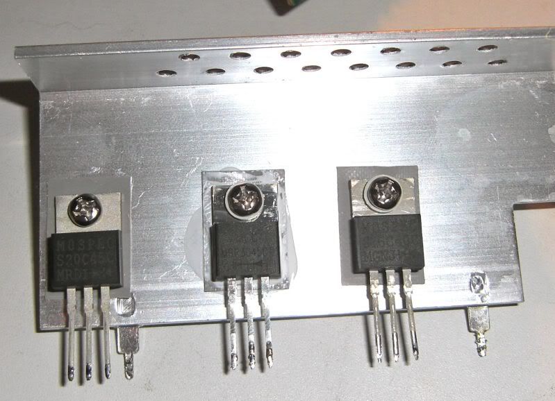
He changes the 12V regulator so he can get 30Amps out of it. My supply is rated for 15A at 12V so, will be good for 13A at 13.8V without modification I guess. The manual for my Magnum Delta Force says it uses 6 Amps max so that's plenty. He also removes the 3.3V and 5V regulators and rewinds the toroid with 18 gauge enamelled copper. I got some of this special wire and may do the same. I am not quite sure though if I need to put on the same number of turns, or if I should put on an many turns as I can. First I need to do some more investigations to see if there is a precise pattern as to when the voltage drop during transmit occurs and if it has any negative effects. So far I'm happy though as I can put the battery back in my van and the radio is working better than it did with the battery.