New expansion - UPD858 SSB chassis

A forum for the discussion of matters of a technical nature. All such activities are undertaken at the readers discretion and own risk. If you don't know what you are doing, don't blame us if it all goes wrong!
lbcomms
Radio Addict
Radio Addict
Posts: 509
Joined: 04 Oct 2015, 08:10
Location: Sydney, Australia

New expansion - UPD858 SSB chassis

Post by lbcomms »

Better rather late than never - the "no SMT" expansion that will fit nearly all SSB capable radios that use a dowmixer type PLL circuit.

First one done is the old uPD858 chassis from the late 1970's. The mod should also work with the uPD2824 (i./e Cobra 146, President AR144)
and the MB8719/MB8734 (i.e. Cobra 148 / 2000) radios with only minor changes, these will be tried as suitable radios come to hand. We already have both a uPD2824 (AR144) and an MB8734(Cobra 148 side mic) radio waiting for installation, and others such as the GRE / REC86345
(Realistic TRC-448) and the NDI (Johnson, Liner, Pace, SBE) are on the eBay / Gumtree shopping list.

No promises as to when the others will be done, we've had a rather busy year with no time for experiments, but hopefully sooner than later.

First up, warning. This is intended for people experienced with RF and digital electronics and are comfortable inside a radio. It is NOT a beginner "cut the orange wire and solder it to the green one to make your radio put out 50 watts" style change.

This works - I've done 4 radios this way in the last week - but I can't control your ability. In short - if you skipped something obvious and fried your own radio, don't blame me. If you are not 100% sure what you are doing, ask here nicely or take it to a competent technician.

This is a work in progress project still under development, and may contain bugs. So don't do this on your primary or only radio just yet.
Any bug or success reports gratefully appreciated though!!!

Now we've got that out the way... back on track.

The requirements we set for this project are:


1) Mod must be reversible, so no cut tracks / drilled holes / dremel butchery. These radios are most valuable in standard form, so mod must be easily undo-able for radio resale.

2) No SMT. Not everyone tinkering with old radios has the ability or equipment to work with these tiny devices.

3) No sensitive analog / RF components such as coils / crystals, and little or no wiring where length of cables is critical.

4) Able to give large amounts of "slide" or add dual coarse/fine clarifiers without drift or instability.

5) All components currently / readily available through online sellers such as Ebay / Amazon, or at a pinch Mouser / E14 / Digikey.

6) Cost of parts under AUS$25 (20 USD / Euro / UKP) including the programming hardware.

Only way to achieve this was by going digital. If you've never used a programmable microcontroller before you might have a bit of a learning curve with these. The only semi-critical piece of equipment needed is a bench type frequency counter, at least 7 digits of resolution will be needed, 8 is better (i.e 1Hz resolution at 30 MHz). Having other high end gear (scope, spectrum analyzer) is nice to align the rest the radio, but is not needed to install the mod.

The oscillator used is claimed to be stable at 10ppm, this works out to within 340Hz at the 27Mhz output frequency. If there is not too much
temperature variation at the radio, such as in a base station, it's adequate for SSB use. For situations where there are extremes - such as in a car
here in Australia where it can get to 50 degrees C (120 Fahrenheit) in the daytime and near freezing at night - we made a stabilizer to make it stable to within a few Hz. It's not included here as it involves tiny SMT component changes but we'll post this later for anyone that wants extreme stability and is able to do the soldering needed.

The heart of the mod is the Adafruit Si5351 programmable oscillator board. This is a tiny board - not mush bigger than a square inch - is a double PLL/VCO that can be programmed over a serial pair of wires to generate any frequency from 8Khz to 160MHz in 1Hz steps. It has 3 outputs but only 2 are used (the third output is not completely independent of the other two).
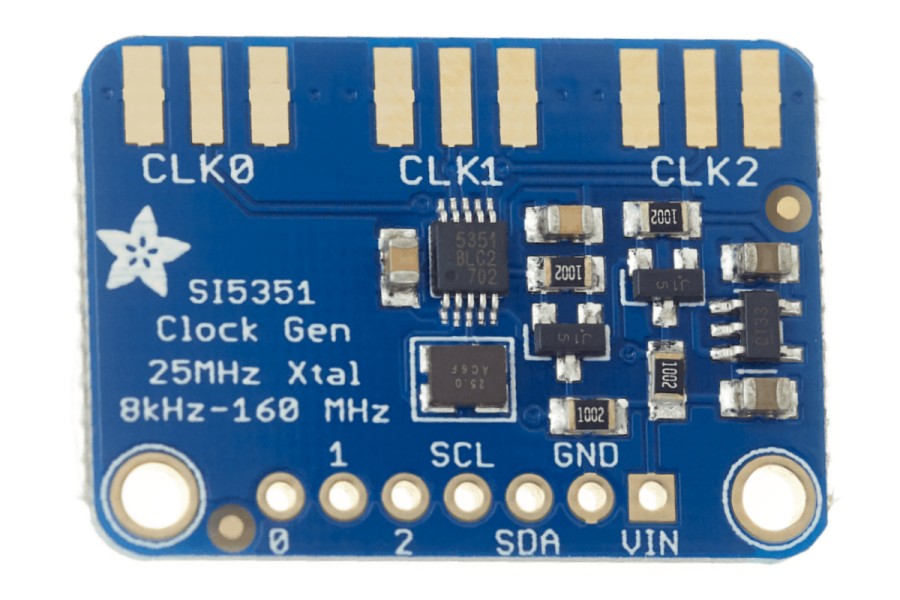
Image
The Adafruit board

The first output (CLK0) is used as a test point to accurately "trim" the new synth onto frequency. The second (CLK1) is used to replace the radios 3 11Mhz downmixer crystals. In the radio, the radios 3 11Mhz downmix oscillators are used to generate the SSB offsets and the small clarifier changes. The VCO operates in the 34MHz region and needs a downmix signal of about 1 MHz due to the low speed of the early dividers in the PLL chip, so the 11 MHz signals are over-driven, generating harmonics,and a filter is used to pass only the third (i.e. 33 MHz). This is then mixed with the 34MHz VCO and the resulting 1 MHz difference signal is fed back to the PLL to lock the loop.

The filter is relatively narrow as it has to reject anything other than 33 MHz. By generating the 33 MHz signal directly, the filter is less critical, and actually needs to be a bit wider so the changes for the different bands don't drop the amplitude of the difference to the point where the uPC858 PLL can no longer achieve lock. It's easy to change the tap on the filter transformer to achieve this, and completely reversible (no track cut needed) if you want to return the radio to standard.

Image
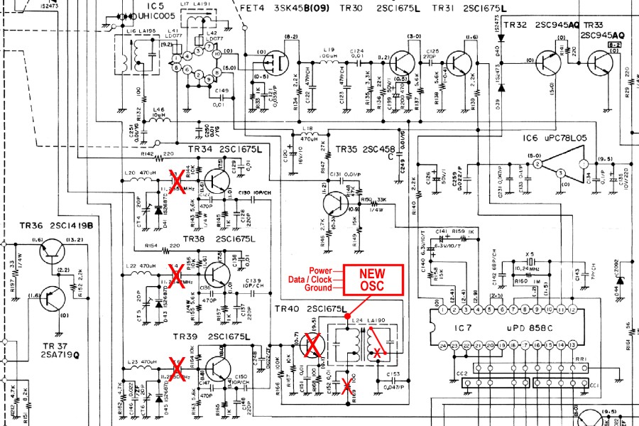
Components removed (large red X) from the original circuit. The centre tap on the transformer can be just de-soldered (small red X).

Image
Removed downmix components and modified transformer tap.
Don't forget to remove the resistor, leaving that in will destroy the adafruit board from over-voltage!

Image
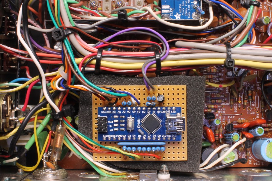
Adafruit board added as close to the downmixer section as possible.
The CLK1 to centre of the removed transistor wire should be kept as short as possible.

Image
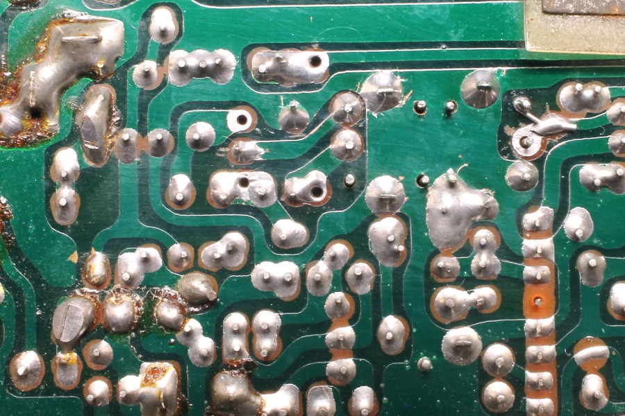
Print side of board, showing the tap change.

To control the board, a microcontroller is needed. A few passives are needed to isolate the 12V and 9V inputs from the 5V maximum rated controller IC. The Arduino Nano is used here, very cheap and has a USB port on it that can be used to tune the radio onto frequency. The 9V and 12V inputs are needed so the radio can tell the radio what mode and band are current, and if it's transmitting or receiving. The coarse and fine clarifier pots also connect to the controller board.

Image
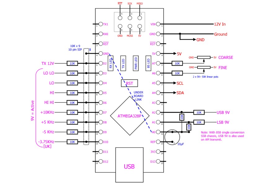
Control board wiring diagram

The wires used are:

TX 12V = 12V on transmit, no voltage on receive. From the Tx/Rx relay.
LO LO = Band A
LO = Band B
MID / Band C = no voltage on LO LO, LO, HII, ot HI HI
HI = Band D
HI HI = Band E
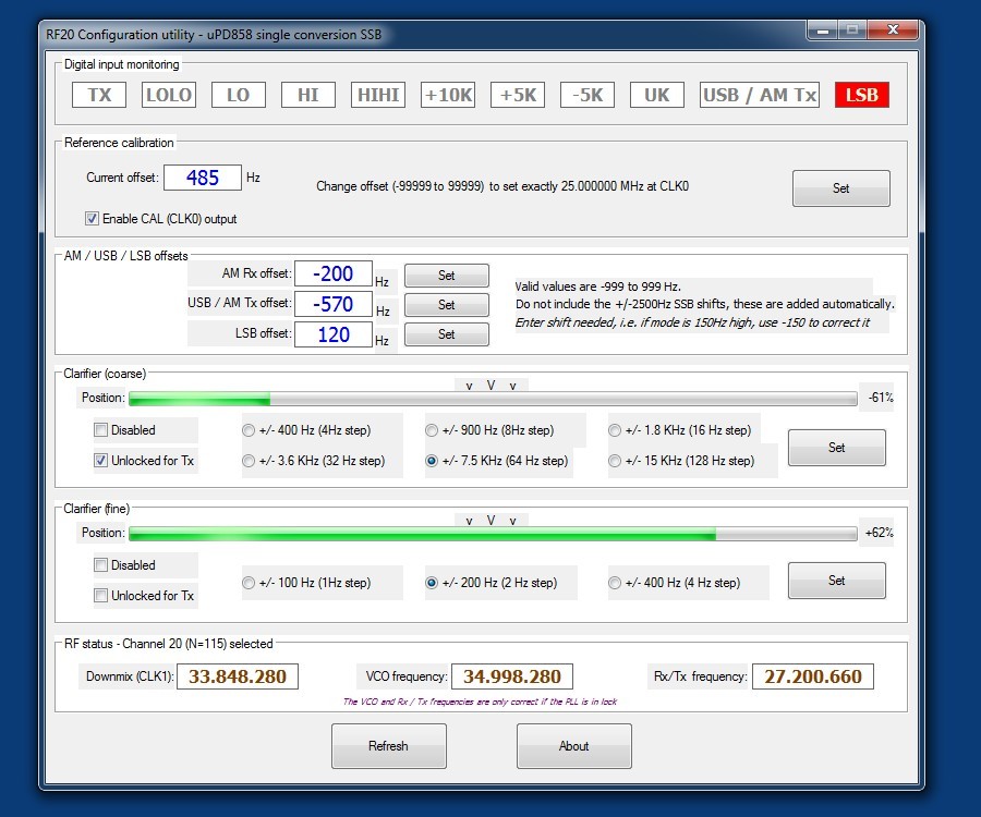
+10KHz, +5KHz, and -5KHz = used to get the gap "A" channels and to get the "zeroes"
UK = 3.75 KHz drop, for example using this on Hi band channel 40 gives UK channel 26 (27.85125 MHz) at centre clarification.

12V in / Ground = power to the controller board
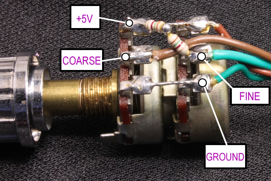
5V OUT = power to the two clarifier pots and the Adafruit board
COARSE / FINE = the "wiper" terminals of the clarifier pots
SCL and SDA = Adafruit board control lines
USB9V = +9V only on USB and on AM Transmit. Available from the mode switch or one of the 220 ohm resistors near the removed crystals.
LSB9V = +9V only on LSB. Available from the mode switch or a 220 ohm resistor near the removed crystals.

Only connect the ones you need. Without complex broadbanding mods, the radio will only cover 3 ranges, i.e. under 1.5MHz of bandwidth.

Image
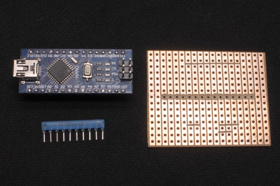
Nano controller board, perfboard, and the SIP resistor.

Image
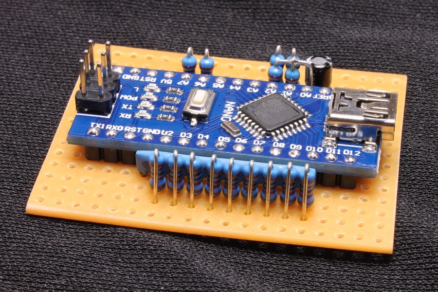
Nano controller board and passives assembled.

Image
Nano controller board bottom link. Forget this and the clarifiers won't work.

< continued below >
lbcomms
Radio Addict
Radio Addict
Posts: 509
Joined: 04 Oct 2015, 08:10
Location: Sydney, Australia

Re: New expansion - UPD858 SSB chassis

Post by lbcomms »

Image
Wired up and temporarily in radio. The 6 pin header was then used to connect the programmer and upload the firmware.

Image
Wiring of the dual clarifier pot.
The original was taped up and left in the radio in case the radio is to be returned to standard sometime in the future.

The fine side was a "log" type and therefore off centre, so a resistance was needed to pull it back to linear operation.
Value was determined by experimentation. The centre terminals should be half voltage (i.e. 2.5V) at the "12 o clock" positions.
Needed a 3K resistor, didn't have one handy so I used a couple of 1.5K 1/8W types in series from fine wiper to 5V.

Wiring was checked with a meter, all correct so all to do now is tune it. Threw a Windows app together to simplify this step.

Image
The app used to tune the board to the radio.

The top row (Digital input monitoring) squares turn red when that input is active. Used to check wiring.

The reference calibration is used to set the master clock (reference) frequency.
This setting is critical to ensure that band changes shift be an exact multiple of 450KHz.

The offsets are used to set the mode offsets precisely. These do the same as what the 3 trimcaps near the removed crystals used to do.

Clarifier (coarse) is used to configure and set the range of the coarse clarifier control.
It can be disabled (i.e. if that wire is not used on your installation), set to receive only, or unlocked for transmit and receive.
The range of the control can be set to one of 6 possible ranges from 400Hz to 15KHz up and down.

The green bar shows the position of the pot and is used as an aid to centre the control using padding resistors if necessary.
The larger "V" mark points to the "12 o clock" (centre) position.
The two smaller marks either side of it show the "dead zone", a small range near the centre where the clarifier control has no effect.

Clarifier (fine) does the same but for the fine clarifier control.
It can be disabled (i.e. not used on your installation), set to receive only, or unlocked for transmit and receive.
The range of the control can be set to one of 3 possible ranges from 100Hz to 400Hz up and down.

The status displays are for information only, showing the downmix, VCO, and the actual frequency the radio is operating on.
The controller has no way of telling what channel is selected, so the numbers are correct only if channel 20 is selected and that the loop is in lock.

Before setting the offsets, the carrier oscillator crystal trimmer capacitors need to be aligned.
The service manual will say to align these to precisely 7.7975000 and 7.8025000 MHz, but these numbers assume the crystal filter is perfect.
It might have been close to spec when the radio was new, but these radios are over 40 years old and it's very rare to see one that is still within specification. If these frequencies don't match the filter, the passband will have one end or the other cut off, resulting in excessively tinny or muffled SSB audio.

They can be aligned by ear by listening to SSB audio. The RF gain needs to be at full and the radio must to be connected to a dummy load.
Put the radio on USB, crank up the volume, and adjust the USB carrier oscillator trim-cap. The tone of the background noise will change.
Initially, adjust the trimmer for lowest tone, and carefully watch the signal meter. If the signal meter starts to rise, you've gone too low,
so readjust the trimmer so the tone gets higher and watch the signal meter fall away. The idea is to get the tone as low as possible without the
carrier passing through the filter and passing through the radios IF stage.

The filter in these radios is common to both AM and SSB - but AM requires double the bandwidth for the same audio frequency response.
This means a compromised filter is used, too wide for SSB and too narrow for AM. Because of this, there is plenty of headroom at the top end for SSB, so by setting the low end as above will give you full response and a bit more.

Once you have USB done, repeat for LSB, then switch between USB and LSB to get the tonal quality the same or as close to the same as practical
on both modes. The radio will be off frequency but this will be corrected next. This method is for single conversion radios only - for dual conversion sets like the Gladiator and the Cobra 148/2000 you'll need to get the tone a bit higher otherwise you'll cut the highs from the audio range.

Turn on the radio and connect the USB port to a computer (only tested on Windows 7 and 10 so far), the computer should download and install
the drivers for the radio (CH340) automatically. Older computers may need the driver to be manually installed.

Once the computer says "your device is ready for use" or something along those lines, launch the configuration program.

Set the four offsets to zero and click "Set", this will need to be done one step at a time.

Put a check mark in the "Enable CAL (CLK0) output" box, and measure the frequency at the CLK0 point on the Adafruit board. This one measured 24.999515 MHz, in other words 485Hz too low. Put "485" in the reference offset value box and click "Set". The frequency at CLK0 went to 25.000001 MHz, close enough. Anything within 10Hz will be OK.

Next, do the AM and SSB offsets. Turn the mic gain all the way down and deliberately misalign the balanced modulator null trimpot for MAX signal. Disable the two clarifier controls and click "Set" for each one.

Transmit on USB and LSB, measuring the frequency. Ours was 570Hz too high on USB and 120Hz too low on LSB.
Set the USB value to "-570" and click "Set", then repeat for LSB, setting that to "120" the same way.
Recheck the transmitted USB and LSB carrier frequencies, they should be very close to spot on.
If OK, reset the balanced modulator null trimpot to the correct "minimum leakage" position.

The AM Rx offset can usually be left at "0", but if you are fussy feed the radio with a signal generator at a low level, 1.5KHz either side
of centre frequency. Give the offset a value that gives the same tone either side - this one needed a 200Hz reduction to centre the filter response.

Image
Screen captured when measuring / setting the LSB offset.

Next, configure the clarifiers the way you prefer.
The owner of this one wanted the coarse 7.5KHz up and down and operational on both transmit and receive, and the fine
clarifier receive only and with 200Hz range either side of centre. Click and Set to save the configuration to the radio.

Image
Clarifiers set to owners taste, and pots moved to verify the settings worked (coarse pot at minus 61% = nearly 5KHz dropped)

Image
Finally, check the switches for correct operation. Here, it's set for high band, 5KHz down, 27.650 MHz on channel 20, lower sideband.

Only thing left to do is align the radio and maybe do a broadbanding mod or two...
lbcomms
Radio Addict
Radio Addict
Posts: 509
Joined: 04 Oct 2015, 08:10
Location: Sydney, Australia

Re: New expansion - UPD858 SSB chassis

Post by lbcomms »

Links for components used

Programmer
https://www.ebay.com/itm/USB-10Pin-to-6 ... G5I96nGEsw
(you'll need the package with both the programmer and the 6 pin adapter)

Controller module
https://www.ebay.com/itm/Nano-V3-0-MINI ... CxjTctUWFg

Resistor array
https://www.ebay.com/itm/50-PCS-A10-103 ... SwU-pXsYfm

Adafruit board (genuine)
https://www.ebay.com/itm/Adafruit-Si535 ... Swq05dRsgu

Adafruit board (clone, cheaper alternative, not tested but should be OK)
https://www.ebay.com/itm/1pcs-CJMCU-535 ... D&LH_BIN=1

Can't see how to post the binaries here, PM if you want them emailed...
User avatar
KlondikeMike
Super Member
Super Member
Posts: 107
Joined: 06 Jan 2014, 03:59
Call Sign: 9WR2000
Location: Edmonton, Alberta, Canada
Contact:

Re: New expansion - UPD858 SSB chassis

Post by KlondikeMike »

Outstanding! Thank you for your hard work and sharing your project with the community.
TM86
Regular
Regular
Posts: 40
Joined: 13 Jul 2015, 02:04
Call Sign: 2TM86

Re: New expansion - UPD858 SSB chassis

Post by TM86 »

This is what art looks like.
User avatar
cb4ever104
Legend
Legend
Posts: 6561
Joined: 28 Jul 2011, 21:26
Location: España

Re: New expansion - UPD858 SSB chassis

Post by cb4ever104 »

Hi Sue .

Can you post back once you've done the 2824 radios . I might use your method for my 2 AR144s .

Thanks

Paul
30TM060
Paul aka "Sammy". (108) PY60 Old Paisley DX Group (RIP Rab Markie)
Ex GM0 , now EA5 .
Handle "Fortune Hunter" back in "the day"
Radios ....? Anything that says "TAIWAN R.O.C" on the back.
lbcomms
Radio Addict
Radio Addict
Posts: 509
Joined: 04 Oct 2015, 08:10
Location: Sydney, Australia

Re: New expansion - UPD858 SSB chassis

Post by lbcomms »

The 2824 radio is next, hopefully we will have that one done within the week. Will post the details here when it's done.
4a0026aleks
Regular
Regular
Posts: 27
Joined: 21 Nov 2016, 17:51
Call Sign: 4a0026

Re: New expansion - UPD858 SSB chassis

Post by 4a0026aleks »

good job! I have exactly the same done in President grant .only I used the AD9850
User avatar
cb4ever104
Legend
Legend
Posts: 6561
Joined: 28 Jul 2011, 21:26
Location: España

Re: New expansion - UPD858 SSB chassis

Post by cb4ever104 »

lbcomms wrote: 10 Jan 2020, 22:33 The 2824 radio is next, hopefully we will have that one done within the week. Will post the details here when it's done.
Thanks Sue . Look forward to seeing it .
30TM060
Paul aka "Sammy". (108) PY60 Old Paisley DX Group (RIP Rab Markie)
Ex GM0 , now EA5 .
Handle "Fortune Hunter" back in "the day"
Radios ....? Anything that says "TAIWAN R.O.C" on the back.
TM86
Regular
Regular
Posts: 40
Joined: 13 Jul 2015, 02:04
Call Sign: 2TM86

Re: New expansion - UPD858 SSB chassis

Post by TM86 »

4a0026aleks wrote: 11 Jan 2020, 06:58 good job! I have exactly the same done in President grant .only I used the AD9850
Any advantages of the AD9850 over the Si5351? Or is it more of what you had on hand situation?
lbcomms
Radio Addict
Radio Addict
Posts: 509
Joined: 04 Oct 2015, 08:10
Location: Sydney, Australia

Re: New expansion - UPD858 SSB chassis

Post by lbcomms »

There are a few reasons we used the 5351 over the 9850 - not necessarily in any particular order:

1) The 5351 is a bit cleaner - the spurs are further from the fund (being a proper PLL with a VCO, not just a divider) and therefore easier to filter out (like in the 858 example, re-purposing the tripler transformer as a bandpass filter).

2) The 9850 would need an input of 3x to 4x the output to stay reasonably clean - input maximum is 125 MHz / 4 = less than the 33MHz needed for the 858 downmix signal. The 5351, being a VCO with a divider, does not have this limitation.

3) 25MHz oscillators (as used by the 5351) are easier to obtain and cheaper than 125MHz (for the 9850) examples where high stability is needed. A 125 meg 1ppm unit costs $35, a 25 meg 0.28 ppm unit costs $9. Nearly 4 times the stability for about a quarter the cost.

4) There are quite a few variations of the 9850 boards on eBay, some no longer available and some are surplus with no guarantee of future supply. The 5351 boards are current new manufacture and an open hardware design, anyone can clone them and they should look, measure (size), and perform the same as the original.

5) The extra outputs on the 5351 boards can be used to replace other crystals where they have failed and difficult to obtain, or where high stability is needed. The Galaxy drift thread radio did that, the 10.6975 MHz oscillator was substituted by the CLK0 output to minimize drift to below audible levels.
CrazyFin
Super Member
Super Member
Posts: 133
Joined: 08 Jan 2014, 12:12
Location: Stockholm, SWEDEN

Re: New expansion - UPD858 SSB chassis

Post by CrazyFin »

@lbcomms: This is sooooo beautiful! :clap:
Thanks for sharing all your knowledge as well as explaining all your work in a very logical and clear way as well as good pictures of your work.

Would this expansion mod be possible to do on Cybernet chassis like PTBM058COX and PTBM121D4X that has the PLL02?

Schematics for both boards attached (PTBM058COX in PDF format and PTBM121D4X in PNG-format).
You do not have the required permissions to view the files attached to this post.
lbcomms
Radio Addict
Radio Addict
Posts: 509
Joined: 04 Oct 2015, 08:10
Location: Sydney, Australia

Re: New expansion - UPD858 SSB chassis

Post by lbcomms »

Yes and no. It will work with the Cybernet radios, but will cause a performance hit where the Galaxy / Ranger / Uniden radios won't.

The reason is the downmix in the Galaxy / Ranger / Uniden boards is a simple downmix that feeds the difference signal to a digital divider to lock the loop. Any noise or jitter will appear at the output of the phase detector but will be removed by the low pass filter before it tunes the VCO.

With the cybernet, the mixer works both ways. The difference (downmix) works as above, but the sum is used too, to generate the local oscillator signal. The noise, jitter, and other unwanteds can therefore appear on the local oscillator signal, degrading the receiver performance and causing an increase in spurs on transmit.

The big question is - by how much. If might be too small to notice, it may be so bad the radio is unusable. Most likely somewhere in between. I'm on the lookout for a Cybernet to experiment with and do some measurements, so we'll know the answer hopefully within a month or two...
User avatar
dt307
Top Poster
Top Poster
Posts: 1250
Joined: 05 Sep 2014, 16:15
Call Sign: 163dt307

Re: New expansion - UPD858 SSB chassis

Post by dt307 »

great work Sue got a mb8719 jack here will be just the job for this
163dt307-chris


“I fear the day that technology will surpass our human interaction. The world will have a generation of idiots.”
― Albert Einstein
lbcomms
Radio Addict
Radio Addict
Posts: 509
Joined: 04 Oct 2015, 08:10
Location: Sydney, Australia

Re: New expansion - UPD858 SSB chassis

Post by lbcomms »

We've got a couple of other radios here - An AR144 / AX144 (uPD2824 PLL) and a side mic Cobra 148 (MB8719 or MB8734 PLL, makes no difference to the mod above), both bought on Gumtree or similar by one of the locals here and donated to the cause. They'll both need at least a full recap and any other repairs such as de-modding to bring them back to standard radios first, so probably won't get to these for another week or so.

What radio is it you have? There are 2 different offset types with that PLL. The single conversion variants use a +/- 2.5KHz SSB shift with a 5KHz wide SSB filter, and others (like our 148) have dual conversion on AM and use a +/- 1.5KHz SSB shift with a 3KHz wide SSB filter. Each variant will need a slightly different firmware.

After the first glitch (Win 10 home issue) we've had 5 more people test the Win app without further issues, so these should be ready in a day or two. If anyone wants to try them PM me here and I'll email them, not sure if we can attach executables on the board. Please don't email direct and ask, we get a lot of spam, frauds, and people we've never heard of wanting detailed technical advice at that address, so it's easy to get lost in the noise...
Post Reply