Ad blocker detected: Our website is made possible by displaying online advertisements to our visitors. Please consider supporting us by disabling your ad blocker on our website.
A forum for the discussion of matters of a technical nature. All such activities are undertaken at the readers discretion and own risk. If you don't know what you are doing, don't blame us if it all goes wrong!
Renovating an old DD. To speed up the process it would be nice to have a circuit diagram. It has a PC-4C7AC board with a D2816 PLL chip. Don't know if that was used in a mobile version or not.
It was a 40 ch AM rig, but it has been modded in the past with a FM board, and a UK40 board consisting and an eprom and a MM55108 PLL chip.
Have reconnected the AM side of the rig (as the wires were still inside the rig), and now have a 3-position switch to select Mid AM, Mid FM, and UK FM.
So anyone got a circuit diagram for this chassis, it would be appreciated
Cheers
Dave the Pixie
73 from Dave the Pixie - 26CT052 - 26TM552 - CB Radioaficionado
Thanks for the diagram pdf. That's going to make my life so much easier
Well it looks like PC-4C7AC, but the "C" may be a badly formed "0". So yes it it must be a PC-407AC.
I do have a picture of the innards. I will have to post it when I have a moment to do so. Which mod interests you the FM modem board or the UK40 board?
Both conversion boards look homemade from the back of someone's shed. Defo not a factory conversion. This is definitely the 40 ch AM, not the 80 ch AM/FM version.
If I have more insights I shall post them
Cheers
Dave
73 from Dave the Pixie - 26CT052 - 26TM552 - CB Radioaficionado
The circuit diagram from CB Tricks has been useful. Shame it isn't complete, but has been helpful.
In the diagram to suggests that the FM modulation needs to be fed into the VCO's varicap diode with a 100k resistor. But the in the conversion of the DD I have here, the 100k resistor is fed into the junction of R71 22k resistor and C95 22n capacitor. I disconnected the 100k and soldered onto the junction of D14 and R71 as suggested in the diagram. Found that there is too much synth (?) noise/hiss on TX. So disconnected 100k and reconnected as I found it. The noise/hiss is now at a bare minimum.
73 from Dave the Pixie - 26CT052 - 26TM552 - CB Radioaficionado
This DD I'm restoring has some strange issues. The UK board is originally designed to go from 27.595 to 27.985 MHz. How bonkers is that
So the original modifier pulled up the 10.240 MHz reference oscillator to get a 6.25kHz shift. They did this by unlocking the delta tune and expanding it to have it +6.25kHz (for the UK 1.25kHz offset) fully c/w, and when fully the other way to allow use on mid band (5kHz offset). This will reduce the sensitivity on the UK band a little bit as the 10.240MHz osc (pulled up to 10.242 MHz) in used for the local osc to the 2nd mixer.
So I have returned the delta tune to its original RX only function. Adjusted the ref osc to the UK offset (+6.25kHz in the case of this rig). Added a transistor switch with a small amount of capacitance (around 30pF) to pull the ref osc onto the mid band offset. The transistor switched by the 3-position band/mode control as mentioned in my first post.
So now can switch from EU-AM, EU-FM & UK-FM without messing!! All I've got to do now is adjust the resistance of the delta tune a little bit to get aligned at 12 o'clock with the transmit frequency.
73 from Dave the Pixie - 26CT052 - 26TM552 - CB Radioaficionado
RadioPixie wrote: What Uniden board did it have originally before the transplant?
A broken one !
To be honest I don't recall... but I suspect it was similar to your Dwight. PC-4C7ac . But there were two Zacharys... using different PLL's so it may have been either. It was AM only, 40 ch. and fried !
Ugs
Doing some quick research on the net It looks like the DD and ZT are the same rig but in different casing. Not forgetting the 2 different versions of both rigs with the uPD858 and uPD2816 PLL chips of course
Unless anyone can prove otherwise
73 from Dave the Pixie - 26CT052 - 26TM552 - CB Radioaficionado
As mentioned on a previous post, I'm a bit concerned with the ability of this UK expansion circuitry to receive and transmit on the same channel. There's about 4/5 kHz different between the two. Not surprising as not only the ref osc injection into the 2nd mixer is slightly off frequency, but the loop mixer (derived from the ref osc) will be off as well.
But i had a brain wave this evening. There's a spare terminal on the 3-position mode/band switch (in the UK-FM position) which has 8 volts on it (because that side of the switch works the transistor switch for the mid band offset). I connected this terminal to cathode of D19 and the DD swang up 4 KHz on receive. But this means that the delta tune is now defunct on the UK band.
So it's much nicer on UK-FM receive now. All a compromise, but better than it was. The DD belongs to a friend, and wants the operation of it as simple as possible. If it was mine i would shouted "F### this piece of s~~~!!!", got the dremel out and would of stuck a SS3900 in it
73 from Dave the Pixie - 26CT052 - 26TM552 - CB Radioaficionado
UGLY_BOB wrote: ↑07 Jun 2012, 12:14
... sorry... wrong post.
I got my Dwights mixed up with my Zacharys
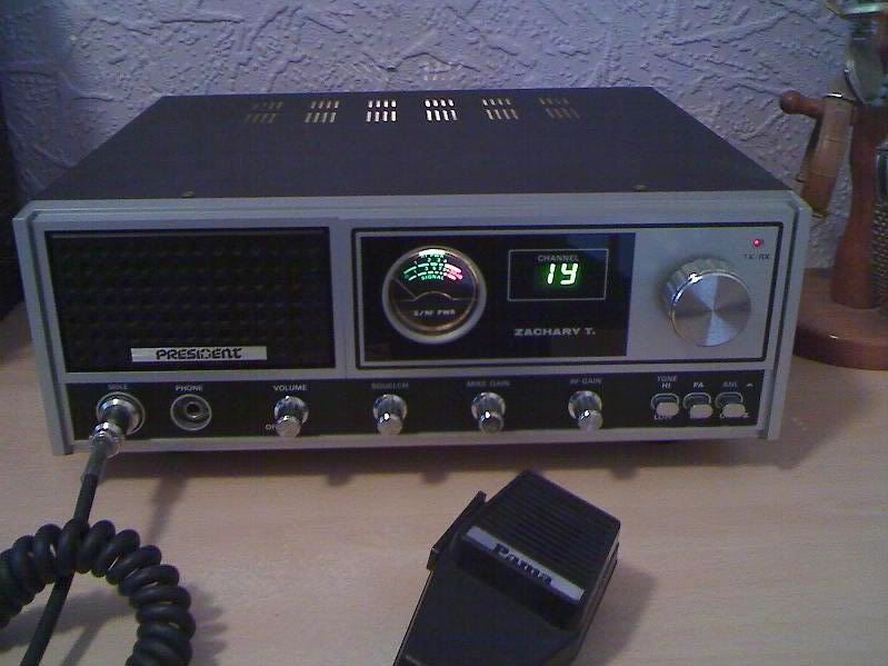
This old Zachary had a Rotel 240 (cybernet 134 board) shoved inside... the green LEDs looked good I thought.
Anyway, back to Dwights...
Ugs
Old post.... I bought an empty case Zachary like that from Tandy's in the 80's.Ex display model, unused. I fitted the internals form a York JCB 863 inside it (PTBM134AOX) with the green LED, along with a Bremi 3amp power supply. Multi coloured ribbon cable to the channel selector. Could it be?