
Hy-Q International Australia still make crystals locally, so could he get come from here? With low quantities coming in at $45 to $60 a pop for common HC/49U crystals, and a website that looks like it hasn't changed since the 90's they are probably not an option. Hmmm, their site is offering payment with the old Australian "Bankcard". Bankcard was shut down in 2005
The existing PLL is the ROM based uPD2816 or an identically functional Cobra branded equivalent. Being ROM based means the "cut the trace and add a switch" modification method used my the 858 / MB8719 / PLL02A won't work.
So could it be done without crystals? Yes it can, by one of two methods. Either change the PLL for a different type which is expandable, or trick the existing one into going more places.
Did a couple of uPD2824 (the SSB only version of the uPC2816) radios with scanning and inbuilt frequency display - swapping the PLL to a modern SMT serially programmed type and rewiring the LED and RF stages to make it do its stuff. Way more than what he needed here, and he has only basic equipment so SMT or RF mods were out of the question.
Method 2 is to trick the existing PLL into going out of band. This is how the crystal boards like the CBCI "EXPANDER 160" did it, so this is the way we went.
The uPD2816 has a divider input ranging from 0.91 to 1.35 MHz (on receive) for channels 1 to 40, and an IF of 10.695 MHz. So for example, to lock the PLL on channel 1:
VCO frequency is 26.965 - 10.695, which equals 16.270 MHz.
The 16.270 MHz VCO signal is also mixed with a downmixer, a fixed frequency of 15.360 MHz. 16.270 - 15.360 = 0.91 MHz, which is then used to lock the radio on channel 1.
For transmit, the IF is changed to 10.240 MHz, which saves Cobra the cost of a 10.695 MHz crystal. They mix the VCO with some spare 10.240 MHz from the reference crystal instead. This means shifting the VCO frequency up by 0.455 MHz on transmit, a pin on the PLL is used to switch the modes. 10.240 divided by 2048 and then multiplied by 91 equals 0.455 MHz, exactly what's needed to lock the loop on transmit.
This is why changing the 10.240 crystal won't help with expansion, too many other things depend on that exact frequency. Doing so would make the channel spacing change and also cause the radio to be transmitting and receiving on two different frequencies...
But: the 15.360 frequency is constant on transmit / receive and on all channels. Therefore, replacing that signal with one say 10KHz higher will cause all 40 channels to both transmit and receive 10KHz higher than they originally did.
That's how the old school Expander crystal boards worked. Changing to a crystal oscillator of 15.810 MHz will shift the radio up by 0.45 MHz. Channel 1 becomes 27.415, one channel above 40. To retain the regular mid band, the original 15.360 MHz signal was switched back in.
The 15.360 signal is also derived from the 10.240 MHz crystal. A second divider in the PLL divides it by two, resulting in a 5.12 MHz squarewave. A squarewave is the original signal and a bunch of odd (3rd, 5th, 7th, and so on) harmonics. A filter (L22 in out example) is tuned to the 3rd harmonic and rejects all the others.5.12 MHz x 3 = 15.360 MHz, and Cobra have saved the price of another crystal.
So a new design which didn't need crystals to generate the new frequencies was needed. Requirements were:
- Cheap, no more than $20 maximum for all parts, but excluding the fitting cost
- No secret or brand X / part numbers rubbed off stuff, a schematic and overlay drawing available
- Available online easily and from multiple sellers
- No SMT or large component swapping / replacing with adapter boards, and no RF stage additions / changes needed
- Installable by someone who can do the old expander crystal boards, with only basic hobbyist grade tools and test equipment
One thing we didn't exclude was the use of programmable devices. To meet all of the above requirements, the installer is going to have to buy a PIC / AVR USB programmer (a once off $10 cost) and learn how to use it. This is not difficult but might mean learning a new skill set if current digital electronics is a mystery to you. In the case of our American friend, his kids are learning robotics at middle school level, they will have no trouble explaining to him how to upload a hex file from a PC to a radio.
He donated one radio to us to experiment with (here in Oz, CB is SSB only, so there were no Cobra 29's to be had here) and come up with a conversion that met all of the above requirements. Radio was a warranty return of his that he'd swapped for one of his customers - it had a failed nightwatch lamp but was untouched, perfect for us as we didn't need the backlight.
We will be keeping it here in case any bugs show up and need updating, and as a development unit in case any requests for changes to the frequencies / hex file happen. The two components used were the Arduino Mini MCU board (under $3 on eBay) and the Adafruit clock generator ($7.95 from Mouser or Adafruit)
The MCU looks at the switches and programs the clock generator to 15.360 MHz if all the switches are open, giving the standard mid band channels.
- If switch A is closed, the frequency is offset down by 5 KHz. This gives the "zero" frequencies, such as 26.960 MHz on channel 1.
- If switch B is closed, the frequency is offset up by 10 KHz. This gives the "alpha" or "RC" frequencies, such as 27.095 MHz on channel 11.
- If switch C is closed, the frequency is offset down by 450 KHz. This gives the "low" band, 26.515 (1) to 26.955 (40).
- If switch D is closed, the frequency is offset up by 450 KHz. This gives the "high" band, 27.415 (1) to 27.855 (40).
The four switches can be used in any combination, for example, closing switches A and D on channel 1 will give 27.410 MHz.
If any of the offsets are not needed, just don't connect a wire to that point.
Downsides:
1) The Adafruit boards are intended for driving digital electronics, not radios, so they drift a bit with temperature.
Accuracy was within 100Hz at 20 degrees C (70 Fahrenheit). At 45 degrees C (115 Fahrenheit) the radio was 290Hz high, and at -10 degrees C (15 Fahrenheit) it was 200Hz low. That is more than good enough for AM where an error of up to 500Hz would be unnoticeable, but it's not stable enough for a good SSB experience.
2) If the Cobra 29 is a version with a delta tune, that control will no longer function correctly. Range will be a quarter of what you had with a stock radio.
3) It will only work with a downmixer type PLL circuit like the one in the Cobra 29. It's not spectrally clean enough to work as a direct local oscillator replacement.
4) It won't work in the SSB versions such as the Cobra 146. The clarifier and USB/LSB offsets will not operate correctly and it will be too drifty for SSB.
An SSB version is on the drawing board. A prototype of that is in another thread (Galaxy ranger drift cure) here. That one uses a very large board with huge distances between components to make prototype changes a lot easier with thru hole style components. The final "version 1" will have a conventional layout and be about a quarter the size.
Stability of the SSB version will be good for up to 280ppb, i.e. worst case 10Hz drift from -10 to +45 degrees C.
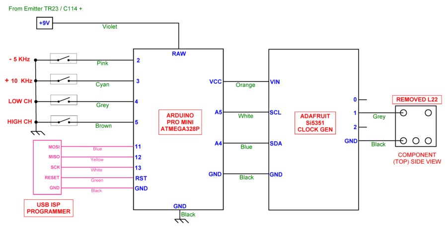
Wiring diagram for the boards and switches
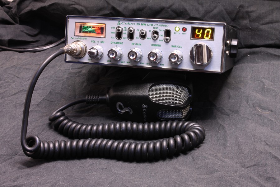
Radio as received from the USA, never opened.

Adafruit clock generator and Arduino MCU board boards - size comparison to an AA battery

switches rewired. Didn't want bits hanging out so we rewired the CH9/19 and the ANL/NB switches

Adafruit board wired up

Adafruit board mounted and wired to where L22 was.
Ground connection was slight different to the drawing, it was connected instead from the other side of the Adafruit board to the radios ground foil.
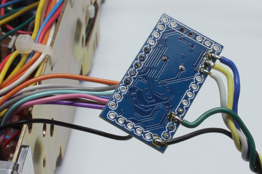
Arduino MCU board with temporary programmer wiring connected

Temporary programmer wiring removed after hex file has been uploaded
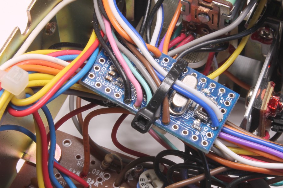
Arduino MCU board secured with a cable tie

Finished install in the development radio
The addin boards were mounted loosely in this case so that it would be easy to make future changes, something more secure should be used if the radio is going into a vehicle.
The VCO was tuned for 1.6 volts for worst case low voltage (low channel 1, receive) and gave 3.6 volts worst case high voltage (high channel 40, transmit). This gave almost a volt of adjustment spare at each end. Last, the RF mixers / stages needed only minor alignment changes to get full power out and good receive sensitivity across all bands...

