Page 1 of 2
Superstar 360FM Photo
Posted: 17 May 2018, 10:02
by radiogaga
Anyone have a high res photo of the vanilla wiring from board to switches/pots on a PB0101AB Chassis?
Thanks
Re: Superstar 360FM Photo
Posted: 17 May 2018, 10:25
by Otter
It's not a picture, but the wiring is detailed in the service manual for the Cobra 148GTL-DX on CB Tricks.
http://www.cbtricks.com/radios/cobra/14 ... g35_36.pdf
Re: Superstar 360FM Photo
Posted: 17 May 2018, 18:53
by 163TM847
The holes for the wires are marked too which is handy, For example "Vol M" would go to middle pin of volume control etc etc.
Re: Superstar 360FM Photo
Posted: 17 May 2018, 21:11
by radiogaga
Great - Thanks guys
Re: Superstar 360FM Photo
Posted: 17 May 2018, 21:15
by radiogaga
Black Spirit wrote: ↑17 May 2018, 18:53
The holes for the wires are marked too which is handy, For example "Vol M" would go to middle pin of volume control etc etc.
I might be missing the markings??? Is it on the link?
Re: Superstar 360FM Photo
Posted: 18 May 2018, 10:54
by Otter
The markings are on the PCB in your radio, not on the wiring diagram.
Re: Superstar 360FM Photo
Posted: 18 May 2018, 15:54
by radiogaga
Didn't know if I was missing something on the diagram too

Thanks all.....
I'm reconstructing a 360FM which has been butchered which is missing there three band switch.... Hens teeth!
The wiring from the switch has been hacked out but the remnants of PINK and possible GREY go to a diode at MX(2). Clearly part of the mod/hack!
I've located MX(1) for Violet
Yellow at SFT ????????
Black at N ??????
If these are right looking to house PINK and GREY?
Thanks
Re: Superstar 360FM Photo
Posted: 18 May 2018, 17:06
by 14CS06
Hello
PINK and GREY here
@+
Claude
Re: Superstar 360FM Photo
Posted: 18 May 2018, 17:44
by radiogaga
14CS06 wrote: ↑18 May 2018, 17:06
Hello
PINK and GREY here
@+
Claude
Thanks

Re: Superstar 360FM Photo
Posted: 19 May 2018, 13:13
by 163TM847
You can get three way band switches from ebay [
https://www.ebay.com/itm/2pc-Rotary-Swi ... 100623.m-1] MX1=LOW BAND, MX2=MID BAND, MX3=HIGH BAND, 8V For band switch comes from the 8v supply on the mode switch, SFT wire that goes to the band switch switches to ground when on Low and Mid band but you can wire SFT directly to ground
Re: Superstar 360FM Photo
Posted: 19 May 2018, 18:01
by radiogaga
Black Spirit wrote: ↑19 May 2018, 13:13
You can get three way band switches from ebay [
https://www.ebay.com/itm/2pc-Rotary-Swi ... 100623.m-1] MX1=LOW BAND, MX2=MID BAND, MX3=HIGH BAND, 8V For band switch comes from the 8v supply on the mode switch, SFT wire that goes to the band switch switches to ground when on Low and Mid band but you can wire SFT directly to ground
Superb, hunted for ages, thanks.
I may come back to when the switch arrives, not sure I follow the last line regarding the Direct grounding.
Re: Superstar 360FM Photo
Posted: 19 May 2018, 19:11
by 163TM847
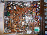
On the band switch there will be your 8v input, then the three bands, then there is a yellow wire that comes up from the main board marked SFT [You will see SFT hole near the 15.000 crystal], This SFT will connect to the band switch on pins 1 and 2 and a ground from input, So when your on Low or Mid the SFT is grounded, But you dont really need to connect the SFT wire to the band switch you could if you wanted too connect it directly to ground.
If SFT is left ungrounded you may have trouble locking the three bands, Well they may lock but you will get a "howl" noise on the bottom end.
DSC00256.JPG
Re: Superstar 360FM Photo
Posted: 21 May 2018, 12:58
by cb4ever104
I love these types of jobs . Stripping down the "front end" , and rebuilding it from scratch . Great fun !

Re: Superstar 360FM Photo
Posted: 21 May 2018, 14:30
by radiogaga
I'm hopeful come the arrival of the new band switch.
Re: Superstar 360FM Photo
Posted: 24 May 2018, 16:23
by currentstatus
More pics..
IMG_5778.JPG
IMG_5777.JPG