Zetagi b132 technical help

The place to talk about specific amateur radio equipment and all types of accessories, fixes, repairs and modification.
User avatar
Ur5by9
Super Member
Super Member
Posts: 118
Joined: 20 Jul 2015, 21:57

Zetagi b132 technical help

Post by Ur5by9 »

I have inherited some equipment which I have been going over and testing out.

I came across a Zetagi B132 base amplifier which is in pristine condition.
Deciding to test this into a dummy load I quickly found out the unit is faulty.

I put 4 watts in and got around 100mw out, I upped this to 10 watts in and still get around 100mw out.

So what I have tested is the unit gets power to the main transformer and the meter on the front is illuminated.
Out of the transformer the board receives around 32V DC
When I put RF power into this the relay clicks however no power is outputted.

I like a challenge and tinker around learning as I go along and wonder if I can be pointed in the right direction.

Connections all seam fine internally and to be honest not a lot exists inside this unit.

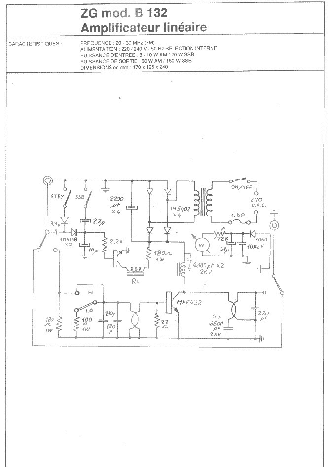
The output driver is an MRF422, If this was faulty would I expect the above results?
Power being fed in must be dissipated somewhere as nothing comes out?

Found a schematic

Image

Some help will be with the greatest of thanks.
mastercare
Super Member
Super Member
Posts: 141
Joined: 28 Feb 2016, 19:17
Call Sign: g4sbx

Re: Zetagi b132 technical help

Post by mastercare »

hi
there are some posts about this amp on the forum 16th october 2014 where it mentions the input sw on back? if the mrf422 has gone open circuit you would prob get no or very little power out..ive just been working on a 2 metre amp which we have had to totally rebuild. with a dvm i would check the supply to the mrf and carefully meter around...failing that you could carefully lift the legs of the final and check on diode probe see the transistor is switching on eg base emitter base collector...u wont get much in circuit cos there is a 22 ohm across base to emitter so you really need to check it out or lifted...go round check the caps diodes etc...hope you suss it...
paul
User avatar
Ur5by9
Super Member
Super Member
Posts: 118
Joined: 20 Jul 2015, 21:57

Re: Zetagi b132 technical help

Post by Ur5by9 »

Hi Paul thanks for the reply, the inherited equipment was my late fathers so the sentimental side means quite a bit to me, I feel I have to make this work for reasons listed. Had my father been around he would have the answer, he always did. Amongst a huge amount of components i have come across an ACRIAN S175-28 Amplifier chip which is rated at a much higher output than the MRF422 would you think I could directly replace this transistor and under run it ? I believe the standard transistor MRF422 is rated at 100w where as the chip I have is rated at 175watts. thoughts are with the greatest of thanks.
User avatar
ghost123uk
Radio Addict
Radio Addict
Posts: 758
Joined: 19 Aug 2012, 13:46
Call Sign: 26TM953
Location: S. Cheshire

Re: Zetagi b132 technical help

Post by ghost123uk »

I had a quick look at the specs and I would say it would likely work in that amp. You won't get the extra power though as that is governed by other parts of the circuit, and anyway, the PSU wouldn't keep up, and even if it could, you wouldn't want to simply shove loads of extra power through the final output filters as they won't have been designed to handle it.

Data sheets for both can be got from my Dropbox here -> https://www.dropbox.com/sh/g8jcoumdwxrr ... xICLa?dl=0

I wonder if your father knew it needed a new output tranny and bought that one for it? From the specs it's a pretty rugged device. I note it says 30V is the max collector voltage for it, I wonder if 2V extra would be risky, what do others reckon?


PS, whip the MRF out anyway to test it with your meter. If you don't know how to do that, just ask.
Last edited by MrWeetabix on 14 Apr 2017, 20:51, edited 1 time in total.
Reason: Changed 'current' to 'Voltage' after a typo by user. change requested by user - MrWeetabix
John, on the S. Cheshire / N. Shropshire border. 26TM953 / muppet handle "Grey ghost"
Don't just monitor, key up and talk, otherwise everyone thinks no one else is out there !!!
User avatar
Ur5by9
Super Member
Super Member
Posts: 118
Joined: 20 Jul 2015, 21:57

Re: Zetagi b132 technical help

Post by Ur5by9 »

Hi Paul thanks for the reply and information.
I took a look at the data sheet and the MRF422 specification indicates maximum 28 V, so although the board is being fed from the transformer at 32V i wonder if in the circuitry this is being reduced, I believe the 1N type diodes can reduce voltage and I see a few in there? and wonder if they are also dropping of some volt's.

I will take the board out tonight and remove the MRF422, I am unsure how to test this to see if it has failed, If you can give me some information
on testing this device that would be great.

I Appreciate the help thank you.
User avatar
Ur5by9
Super Member
Super Member
Posts: 118
Joined: 20 Jul 2015, 21:57

Re: Zetagi b132 technical help

Post by Ur5by9 »

Update, I went ahead and replaced the MRF422 with the ACRIAN S175-28

Put it all back together and it works into a dummy load, 5 watts in returned around 40 out and 10 watts gives 100 watts
The meter on the front panel was fairly generous so I calibrated this to my power meter using the internal trimmer.

I didn't try this on SSB not quite sure what it should output?
One thing that does bother me the earth wire from the mains plug is tagged to the main board soldered in place however the chassis of the unit
is not earthed at all, no continuity between the earth pin and chassis, should I rectify this or would there be a specific reason this is done that way?

Thanks for the help and advice.
User avatar
ch25
Top Poster
Top Poster
Posts: 1675
Joined: 03 Dec 2016, 11:07
Call Sign: Lemmy
Location: Poland

Re: Zetagi b132 technical help

Post by ch25 »

That is C class amp. For SSB you should add bias circuit.
WE ARE MOTÖRHEAD, AND WE PLAY ROCK N' ROLL
You can't have too many antennas...
User avatar
ghost123uk
Radio Addict
Radio Addict
Posts: 758
Joined: 19 Aug 2012, 13:46
Call Sign: 26TM953
Location: S. Cheshire

Re: Zetagi b132 technical help

Post by ghost123uk »

I can't see any reason why the chassis & case should not be earthed, for safety. If it where mine I would connect the mains earth to the casing as well. Anyone else got any views on this ?

Re SSB. From what I read into it, it will work just fine on SSB. It already has the time delay switch built in and bias should not be a problem (imho of course). As for output, on SSB, just whistle loud into the mic and see what you get on the meter. Take care not to over drive it from the rig though. I would say 10W in is absolute maximum. Remember, pushing it to the limit to get 100W out, as opposed to say 80W out, is barely going to affect your TX range at all. The rough guide is, doubling your output power gives only about 10% increase in range.

Glad you got it up and running :)
John, on the S. Cheshire / N. Shropshire border. 26TM953 / muppet handle "Grey ghost"
Don't just monitor, key up and talk, otherwise everyone thinks no one else is out there !!!
User avatar
Admiral
Legend
Legend
Posts: 10109
Joined: 08 Mar 2011, 21:20
Call Sign: 26TM157
Location: MK-UK

Re: Zetagi b132 technical help

Post by Admiral »

ghost123uk wrote:I can't see any reason why the chassis & case should not be earthed, for safety. If it where mine I would connect the mains earth to the casing as well. Anyone else got any views on this ?
I'm no expert so not making a suggestion, just offering an opinion, but the Earth on a domestic system is not there to protect components but to protect humans from death if the unit has a metal case and uses 240v mains.

It's odd that you have no continuity from the PCB to ground as I would have thought the outer shielding of the inputs and outputs would be common ground and go to the outside of the SO259s and thus to the cabinet. But I know very little so wise to ignore me.
Winner of the 2017 IBTL 'Summer Sizzler' competition
User avatar
Ur5by9
Super Member
Super Member
Posts: 118
Joined: 20 Jul 2015, 21:57

Re: Zetagi b132 technical help

Post by Ur5by9 »

I will go ahead and fit a proper earth to the chassis for safety.
After a short test into the dummy load I did notice that the heatsink on the back is getting which I would
consider extremely warm, I used heatsink compound and the OP transistor is making a good contact with the heatsink.

I feel if this was to be in operation at the heat generated it surely would not last any length of time.
From the circuit diagram above can anyone tell me how to measure the volts across the Transistor as its operating voltage should
be 30V going by the data sheet and Id like to find a solution as to why it is getting so hot.

Also to test the voltage does the unit have to be in a working state IE giving out 100W
Or will the voltage be constant across the Transistor in or out of transmit.

Thanks for all the great feedback and assistance.
User avatar
ghost123uk
Radio Addict
Radio Addict
Posts: 758
Joined: 19 Aug 2012, 13:46
Call Sign: 26TM953
Location: S. Cheshire

Re: Zetagi b132 technical help

Post by ghost123uk »

The voltage on the output final will be present regardless of whether it is in TX or RX state. Measure the voltage between the collector and the emitter (which is also "earth") whilst not in TX mode. Let us know what you get. The diodes you mention further up this thread are simply the rectifier circuit and are not there to drop voltage.

As I mentioned earlier, don't push it to the (100W) limit. (see edit in green) Not worth it. It will last a lot longer if you keep it a good few percent below max. EDIT = by that I meant the max rating of the circuit and especially the heat-sink, not your new transistor. You could very easily fit a thermostatically operated computer fan to the heat-sink.

~~~~~~~~~~~~~~~~~~~~~~~~~~~~~~~~~

Admiral, from what I have seen and read on here, your input has always been sound, so why the "But I know very little so wise to ignore me" ?
John, on the S. Cheshire / N. Shropshire border. 26TM953 / muppet handle "Grey ghost"
Don't just monitor, key up and talk, otherwise everyone thinks no one else is out there !!!
mastercare
Super Member
Super Member
Posts: 141
Joined: 28 Feb 2016, 19:17
Call Sign: g4sbx

Re: Zetagi b132 technical help

Post by mastercare »

hi well it looks like your well on your way to restoring your old amp..<I believe the 1N type diodes can reduce voltage> yes your right diodes often used to drop a small voltage about .6v each on on average...
good luck..
paul
User avatar
Ur5by9
Super Member
Super Member
Posts: 118
Joined: 20 Jul 2015, 21:57

Re: Zetagi b132 technical help

Post by Ur5by9 »

Slight update, after finding the the unit has no earth i discovered that the mains cable had a break where the cable
enters the amplifier at the plastic gromit, This has now been replaced with a much better cable and the earth is now fine between the chassis.

I measured the voltage feeding the OP Transistor and it sits at 31.9 V which is more than the recommended specification, okay its not a huge amount more however I think I will put in x3 N1 type diodes to bring this down a little in case it is also contributing to the amount of heat and stop it being a convection heater.

I will continue to update and appreciate all the feedback and guidance.
Its great to find a nice helpful community to share knowledge and best practise.
wa10
Top Poster
Top Poster
Posts: 1346
Joined: 19 Feb 2008, 00:37

Re: Zetagi b132 technical help

Post by wa10 »

You are mixing test voltage up with rated voltage,
32v off load is fine, its below the rated collector emitter voltage of either transistor plus its unregulated, it will drop under load,

best place to measure collector voltage under load is at the power supply side of the choke feeding the collector,

you won't get the same power output or efficiency as the datasheet test circuit because that's a proper single ended circuit optimised for load impedance at the test voltage,
bv132 uses a broadband transformer like half of a push/pull design that can't be optimised for whatever supply voltage you have under load. your stuck with fixed transformer ratios.
W8JI
"An antenna with a poor ground using few radials cannot have a support mast grounded to the radial common point (at least it shouldn't if designed properly) There is no exception to this!
User avatar
ghost123uk
Radio Addict
Radio Addict
Posts: 758
Joined: 19 Aug 2012, 13:46
Call Sign: 26TM953
Location: S. Cheshire

Re: Zetagi b132 technical help

Post by ghost123uk »

He's right you know :thumbup:

I looked at the data sheet again and the max collector to emitter voltage is shown as 60V (not 28V as I quoted earlier up here) so nothing to worry about voltage wise.

Ta for the correction WA10 :thumbup:
John, on the S. Cheshire / N. Shropshire border. 26TM953 / muppet handle "Grey ghost"
Don't just monitor, key up and talk, otherwise everyone thinks no one else is out there !!!
Post Reply