Spectrum analyser guru wanted! :)

Do you enjoy making your own equipment or antennas? Discuss construction and design in here.
Post Reply
Basil
Super Member
Super Member
Posts: 110
Joined: 19 Jan 2012, 21:48
Call Sign: 2E0ILY
Location: Shropshire

Spectrum analyser guru wanted! :)

Post by Basil »

Been having a play with my HP8468B SA and HP8444A tracking gen. Tried
measuring something commercial that should be built right ;) Getting a
very odd flat trace where moving the inductor core has very little
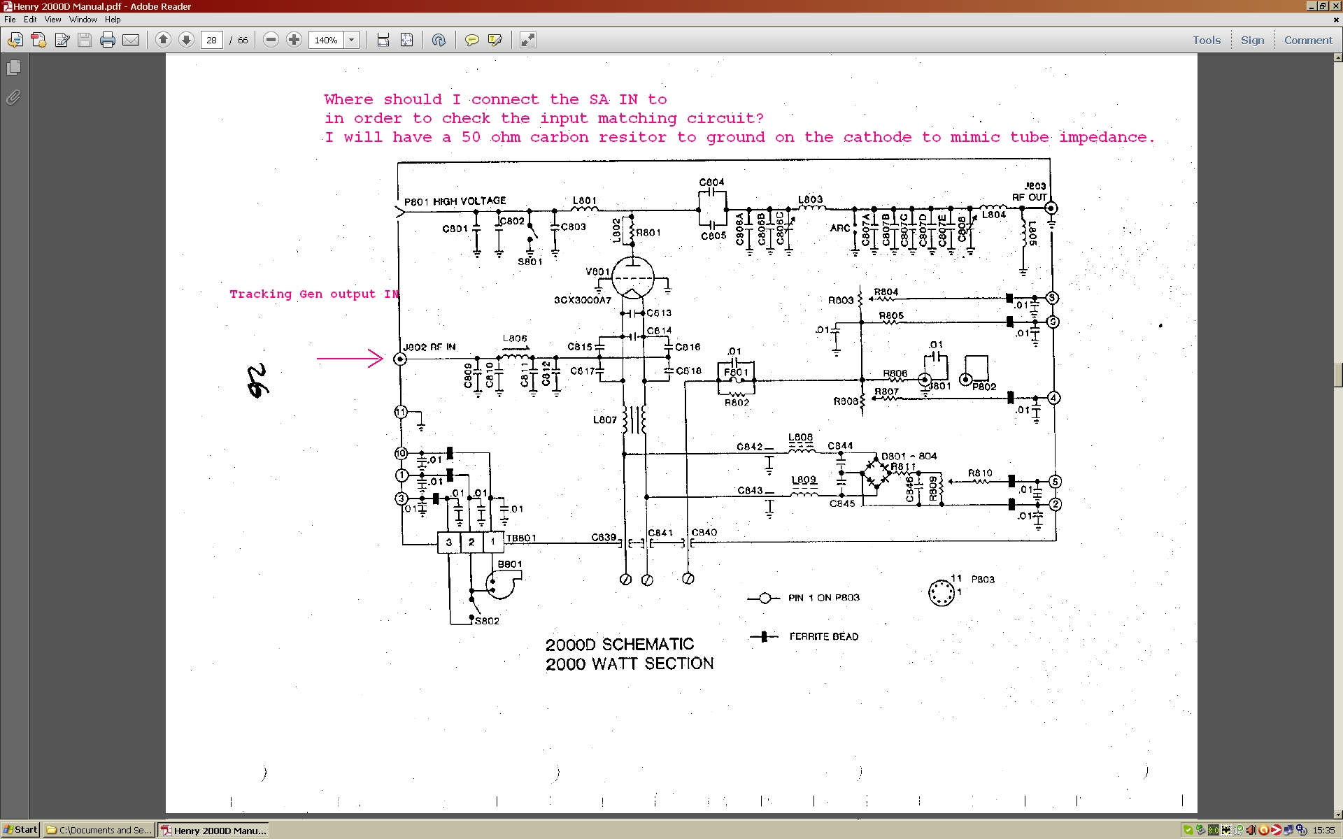
effect. Am I doing this right? Amp I am testing the measurement procedure on is built for 27 MHz as an RF
Generator. Just using it as I know the input circuit should work, as
I am none too confident about a home brew one <LOL>
Tube input impedance is circa 50 ohms. Thanks!
input.jpg
SA.JPG


http://www.gatesgarth.com/input.jpg

http://www.gatesgarth.com/SA.JPG
You do not have the required permissions to view the files attached to this post.
normal
Radio Addict
Radio Addict
Posts: 676
Joined: 07 Oct 2007, 22:18

Re: Spectrum analyser guru wanted! :)

Post by normal »

Some more details will help.

Do you mean an HP8568B?

As I'm sure you know if you connect the output of an transmitter or amplifer producing a few watts directly to the input of a spectrum analyser you will destroy the input circuit in the spectrum analyser, typically either burning the resistors in the input attenuator or blowing the input buffer.
You schematic shows a 3000watt tube.
Presumbly you are using a dummy load with a pickup or a big attenuator between the amp and you analyser?

What do you mean by a flat trace? Do you mean you just see the noise floor as if the spectrum analyser has no input ?

What power level are you testing at from the tracking generator?

I could be wrong but it look to me like that grounded grid amplifer will operate in class C unless you apply some bias so I suspect it will need 20 or 30 watts input to get significant output.

Also I'm sure you realise how dangerous the high voltage supply for somthing like that is.
Basil
Super Member
Super Member
Posts: 110
Joined: 19 Jan 2012, 21:48
Call Sign: 2E0ILY
Location: Shropshire

Re: Spectrum analyser guru wanted! :)

Post by Basil »

I am testing it cold, using the tracking gen and SA as a poor man's VNA. The output of the TG is fed into the input of the amp, no power supply is even connected to it. I am then trying to see if the tuned input circuit can be tweaked to resonance with the coils trimmer core, and looking at the output with the SA. Yes, it's an old HP8568B with an HP8444 TG with a home built 500 MHz oscillator added to give it the missing Option 059 needed to make it work with an 8568B. It measures low pass filters and such like just fine, but my technique is flawed here, I am pretty sure. I am not connected a powered up and working 2kW RF generator into the SA input, fear not ;) I am pretty sure this cold testing of a tuned input circuit is possible, but I need some help as to how it should be done. Cheers.
normal
Radio Addict
Radio Addict
Posts: 676
Joined: 07 Oct 2007, 22:18

Re: Spectrum analyser guru wanted! :)

Post by normal »

that looks like a classic pi section three element low pass filter circuit to me.
With a resistive load on the end I'd expect the response to look like a low pass filter rather than have a sharp peak at a particular frequency.
juniorjack
Regular
Regular
Posts: 21
Joined: 18 Jun 2011, 20:20

Re: Spectrum analyser guru wanted! :)

Post by juniorjack »

Basil wrote:I am pretty sure this cold testing of a tuned input circuit is possible, but I need some help as to how it should be done. Cheers.
Hi,

I have tuned output low pass filters like this, you should get some kind of spike, not a flat line. Maybe your tracking gen range is too narrow ?

BR
Basil
Super Member
Super Member
Posts: 110
Joined: 19 Jan 2012, 21:48
Call Sign: 2E0ILY
Location: Shropshire

Re: Spectrum analyser guru wanted! :)

Post by Basil »

I have had some success using a directional coupler, but more success just driving it with my TS-590 with a dummy load on the output of the tuned circuit. I think actually driving it gives a more meaningful result. The input impedance of the valve i near as damn it 50 Ohms. Next step is to try the amp with power applied into a load. Carefully.... the voltages are a bit worrying!

Thanks for the feedback.
Post Reply